Table of Contents
Advertisement
Quick Links
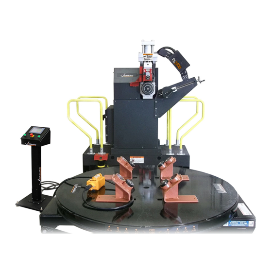
OPERATING AND MAINTENANCE INSTRUCTIONS MANUAL
RG5200i Pipe Roll Grooving Tool
Failure to follow instructions and warnings could result in death or serious personal injury, property damage, and product damage.
• Before operating or servicing any pipe preparation tools, read all instructions in the operating and maintenance manual and all warning
labels on the tool.
• Wear safety glasses, hardhat, foot protection, and hearing protection while working around pipe preparation tools.
• Save the operating and maintenance manual in a place accessible to all operators of the tool.
If you need additional copies of any literature, or if you have questions concerning the safe and proper operation of any pipe preparation tools,
contact Victaulic, P.O. Box 31, Easton, PA 18044-0031, Phone: 1-800-PICK VIC, E-Mail: pickvic@victaulic.com
TM-RG5200I REV_C
WARNING
Original Instructions
TM-RG5200i
OGS
Advertisement
Table of Contents

Subscribe to Our Youtube Channel
Related Manuals for Victaulic AGS TM-RG5200i


Summary of Contents for Victaulic AGS TM-RG5200i
- Page 1 • Save the operating and maintenance manual in a place accessible to all operators of the tool. If you need additional copies of any literature, or if you have questions concerning the safe and proper operation of any pipe preparation tools, contact Victaulic, P.O. Box 31, Easton, PA 18044-0031, Phone: 1-800-PICK VIC, E-Mail: pickvic@victaulic.com Original Instructions...
-
Page 2: Table Of Contents
14 - 16-inch/355 .6 - 406 .4-mm Pipe (AGS Specifications) . . . . . . 21 Explanation of Readings Within Victaulic Specifications . . . . . . . . . . . 24 Explanation of Readings Not Within Victaulic Specifications . -
Page 3: Operator Safety Instructions
. area well lit . Allow sufficient space to operate the tool properly . 10. Use only Victaulic replacement parts and accessories. Use of any Ground the tool to protect the operator from electric shock. Tool other parts may result in a voided warranty, improper operation, components are grounded to the frame of the tool . -
Page 4: Introduction
Upon receipt of the tool, verify that all necessary parts are included . If any parts are missing, contact Victaulic . manual, contains trademarks, copyrights, and/or patented features that are the exclusive property of Victaulic Company. RG5200i Container Contents The RG5200i is designed for roll grooving carbon steel pipe in sizes Qty. -
Page 5: Tool Nomenclature
SECTION I • Tool Nomenclature TM-RG5200I REV_C... - Page 6 • Drawings and/or pictures in this manual may be exaggerated for clarity. • The tool, along with this operating and maintenance instructions manual, contains trademarks, copyrights, and/or patented features that are the exclusive property of Victaulic. Slide (Houses Pipe Revolution...
-
Page 7: Tool Dimensions And Weights
SECTION II • Tool Dimensions and Weights • Lifting Requirements • Tool Setup • Workspace Requirements • Placement of Tracks for the VAP131R Hydraulic, Adjustable Pipe Stand • VAP131R Hydraulic, Adjustable Pipe Stand Placement • Control Station Placement • Proximity Scanner Typical Range TM-RG5200I REV_C... - Page 8 TM-RG5200i / RG5200i Pipe Roll Grooving Tool / Operating and Maintenance Instructions Manual TOOL DIMENSIONS AND WEIGHTS 74 inches 1880 mm 37 inches 940 mm 43 inches 1092 mm 31 inches 787 mm 45 inches 1143 mm 12 inches 305 mm 18 inches 457 mm LIFTING REQUIREMENTS...
-
Page 9: Tool Setup
TM-RG5200i / RG5200i Pipe Roll Grooving Tool / Operating and Maintenance Instructions Manual TOOL SETUP Remove all components from the packaging, and verify that all WARNING items are included . Refer to the “Receiving the Tool” section . • DO NOT turn on the main power supply to the tool until Select a location for the tool, control station, and pipe stand by instructed otherwise. -
Page 10: Adjustable Pipe Stand
TM-RG5200i / RG5200i Pipe Roll Grooving Tool / Operating and Maintenance Instructions Manual PLACEMENT OF TRACKS FOR THE VAP131R HYDRAULIC, ADJUSTABLE PIPE STAND CAUTION • The VAP131R Hydraulic, Adjustable Pipe Stand and tracks must be used to support pipe and are critical to proper tool operation. •... -
Page 11: Vap131R Hydraulic, Adjustable Pipe Stand Placement
TM-RG5200i / RG5200i Pipe Roll Grooving Tool / Operating and Maintenance Instructions Manual VAP131R HYDRAULIC, ADJUSTABLE PIPE STAND PLACEMENT Place the centerline of the VAP131R approximately 6 inches/152 mm back from the middle of the pipe length . Refer to the drawing shown below . -
Page 12: Control Station Placement
. The typical range is shown in the graphic below and can be surface . adjusted by a Victaulic representative, as required, during setup and commissioning . The control station must be placed outside this range in order for the tool to operate . -
Page 13: Power Requirements And Hookup
SECTION III • Power Requirements and Hookup TM-RG5200I REV_C... - Page 14 TM-RG5200i / RG5200i Pipe Roll Grooving Tool / Operating and Maintenance Instructions Manual POWER REQUIREMENTS AND HOOKUP DANGER • ONLY QUALIFIED ELECTRICIANS SHALL CONNECT INCOMING POWER TO THE TOOL, IN ACCORDANCE WITH NATIONAL AND LOCAL ELECTRICAL CODE REQUIREMENTS. • To reduce the risk of electric shock, check the tool and electrical source for proper grounding.
-
Page 15: Preparing Pipe For Grooving
SECTION IV • Preparing Pipe for Grooving • Minimum Pipe Length Requirements TM-RG5200I REV_C... - Page 16 RG5200i Roll Grooving Tools are capable of grooving short pipe lengths . Refer to the following table, which identifies the minimum pipe length requirement per pipe size . NOTE: Grooved pipe nipples, shorter than those listed in the following table, are available from Victaulic .
-
Page 17: Checking And Adjusting The Tool Prior To Operation
SECTION V • Checking and Adjusting the Tool Prior to Operation • Adjusting the Roll Guards • Pipe Stabilizer Adjustment TM-RG5200I REV_C... - Page 18 . The pipe must rest directly on top of the roll and Every Victaulic RG5200i Roll Grooving Tool is checked, adjusted, and must not be skewed to one side or the other . Refer to Section II for tested at the factory prior to shipment .
- Page 19 • The roll guards must be spaced properly by using the appropriate guard setting pad. • DO NOT attempt to use damaged roll sets. Contact Victaulic for replacement parts. • Verify that the lower-roll retaining bolt is tight and that the upper shaft is locked in position.
- Page 20 TM-RG5200i / RG5200i Pipe Roll Grooving Tool / Operating and Maintenance Instructions Manual Pipe Stabilizer Adjustment NOTE: DO NOT adjust the stabilizer roller too far inward, since it will skew the pipe to the left and off center, resulting in excessive pipe-end WARNING flare .
- Page 21 SECTION VI • Fully-Automated Grooving Operation • Explanation of Readings Within Victaulic Specifications • Explanation of Readings Not Within Victaulic Specifications • Grooving a Partially-Grooved Pipe End • Semi-Automated Grooving Operation TM-RG5200I REV_C...
-
Page 22: Fully-Automated Grooving Operation For 4 - 12-Inch
TM-RG5200i / RG5200i Pipe Roll Grooving Tool / Operating and Maintenance Instructions Manual FULLY-AUTOMATED GROOVING OPERATION Twist and pull up on the red “EMERGENCY STOP” button located FOR 4 - 12-INCH/114.3 - 323.9-MM PIPE on the control station . (OGS SPECIFICATIONS) AND 14 - 16-INCH/ 355.6 - 406.4-MM PIPE (AGS SPECIFICATIONS) Verify that all previous sections in this manual have been followed . - Page 23 TM-RG5200i / RG5200i Pipe Roll Grooving Tool / Operating and Maintenance Instructions Manual From the “SELECT SCHEDULE AND SIZE” screen, select the Press the yellow “HOME GROOVE HEAD” bar on the control nominal pipe size and pipe wall schedule . station screen to turn on the tool’s hydraulic system and initialize the tool .
- Page 24 TM-RG5200i / RG5200i Pipe Roll Grooving Tool / Operating and Maintenance Instructions Manual NOTICE NOTICE • A “Moving Ram to Touch Position” message will appear at the • The main shaft will begin to rotate clockwise at a reduced bottom of the screen. speed.
-
Page 25: Explanation Of Readings Within Victaulic Specifications
The control station screen will show an image of the pipe end with a go or no-go indicator for each dimension . The screen shown below indicates that all dimensions fall within Victaulic specifications and that After acknowledgment, the control station screen will show an image of no additional action is required . -
Page 26: Grooving A Partially-Grooved Pipe End
TM-RG5200i / RG5200i Pipe Roll Grooving Tool / Operating and Maintenance Instructions Manual GROOVING A PARTIALLY-GROOVED PIPE END If a partially-grooved pipe end is inserted onto the lower roll, the pipe will fail the initial outside diameter check . To override the initial outside diameter check, press the “MAINTENANCE”... -
Page 27: Semi-Automated Grooving Operation For 18 - 24-Inch
TM-RG5200i / RG5200i Pipe Roll Grooving Tool / Operating and Maintenance Instructions Manual SEMI-AUTOMATED GROOVING OPERATION Using the PT-100A Go/No-Go Grooved Pipe Diameter Tape, FOR 18 - 24-INCH/457 - 610-MM PIPE measure the “C” Groove Diameter . (AGS SPECIFICATIONS) In semi-automated mode for grooving 18 - 24-inch/457 - 610-mm pipe •... -
Page 28: Groove Diameter Within Specification
TM-RG5200i / RG5200i Pipe Roll Grooving Tool / Operating and Maintenance Instructions Manual Groove Diameter Within Specification NOTICE Indicates “C” Groove Diameter is within specification 20 O.D. (508,0) “C” Groove Diameter Range • When the “GROOVE IN SPEC DO NOT ADJUST” button (a) and then the “SUBMIT”... -
Page 29: Adjustment May Be Needed
TM-RG5200i / RG5200i Pipe Roll Grooving Tool / Operating and Maintenance Instructions Manual Groove Diameter Within Specification – Adjustment May Re-insert the pipe end onto the lower roll and initiate the grooving be Needed process by pressing the “YES” button on the following screen . NOTICE Indicates “C”... -
Page 30: Groove Diameter Too Shallow
TM-RG5200i / RG5200i Pipe Roll Grooving Tool / Operating and Maintenance Instructions Manual Groove Diameter Too Shallow Re-insert the pipe end onto the lower roll and initiate the grooving process by pressing the “YES” button on the following screen . If the “C”... - Page 31 TM-RG5200i / RG5200i Pipe Roll Grooving Tool / Operating and Maintenance Instructions Manual After the tool has completed the re-grooving process, measure the “C” Groove Diameter again with the PT-100A Go/No-Go Grooved Pipe Diameter Tape . If the new “C” Groove Diameter measurement is within specification, press the “GROOVE IN SPEC DO NOT ADJUST”...
-
Page 32: Groove Diameter Too Deep (Reject Pipe End Immediately)
TM-RG5200i / RG5200i Pipe Roll Grooving Tool / Operating and Maintenance Instructions Manual Groove Diameter Too Deep NOTICE (Reject Pipe End Immediately) • After pressing the “SUBMIT” button, the following screen will appear on the control station. At this point, a new pipe of the If the “C”... -
Page 33: Extracting Data Via The Usb Connection
SECTION VII • Extracting Data Via the USB Connection TM-RG5200I REV_C... - Page 34 TM-RG5200i / RG5200i Pipe Roll Grooving Tool / Operating and Maintenance Instructions Manual EXTRACTING DATA VIA THE USB CONNECTION After double-clicking the groove data file, a text file will open . The RG5200i Roll Grooving Tool’s data extraction feature provides the user with a means to view and organize grooving data .
-
Page 35: Roll Changing
SECTION VIII • Roll Changing • Lower Roll Removal • Upper Roll Removal • Upper Roll Installation • Lower Roll Installation TM-RG5200I REV_C... - Page 36 • Always verify that a properly-matched roll set is installed on the tool. Failure to follow these instructions may cause grooves that are not within Victaulic specifications, resulting in joint failure, personal injury, and property damage. RG5200i roll grooving tools are designed with rolls to accommodate several pipe sizes and materials, which eliminates the need for frequent roll changes .
- Page 37 TM-RG5200i / RG5200i Pipe Roll Grooving Tool / Operating and Maintenance Instructions Manual Lower Roll Removal Upper Roll Removal 15/16 Using a -inch wrench, loosen the lower-roll retaining bolt . Adjust the front roll guard, if necessary, to uncover the upper shaft completely .
- Page 38 • To prevent interference with the laser, verify that no grease is present on the outside surface of the upper roll. Failure to follow these instructions could result in measurement errors and pipe that is grooved to dimensions that do not conform to Victaulic specifications. TM-RG5200I REV_C...
- Page 39 Failure to follow this instruction could result in measurement errors and pipe that is grooved to dimensions that do not conform to Victaulic specifications. Turn on the main power supply to the tool, then twist and pull up on the red “EMERGENCY STOP” button located on the control station .
- Page 40 TM-RG5200i / RG5200i Pipe Roll Grooving Tool / Operating and Maintenance Instructions Manual Press the “PARK RAM” button on the control station’s Grease the upper shaft bearings, as shown, by applying grease maintenance screen . Verify that the upper roll/slide advances and through the lubrication fitting on the front of the upper shaft .
-
Page 41: Maintenance
SECTION IX • Maintenance • Recommended Lubricants TM-RG5200I REV_C... - Page 42 . NOTE: Hydraulic oil and the hydraulic oil filter should be replaced annually or every 2000 hours of operation, whichever comes first . Contact Victaulic when the tool is ready for hydraulic oil and filter replacement .
- Page 43 TM-RG5200i / RG5200i Pipe Roll Grooving Tool / Operating and Maintenance Instructions Manual RECOMMENDED LUBRICANTS NOTICE • The products listed below are recommendations only. Victaulic does not endorse, sponsor, or have any affiliation with the following manufacturers. • Always verify that the grease or oil is suitable for the intended service by referring to the product’s Safety Data Sheet (SDS).
- Page 44 TM-RG5200i / RG5200i Pipe Roll Grooving Tool / Operating and Maintenance Instructions Manual MAINTENANCE NOTES Operator Date Maintenance Performed Comments TM-RG5200I REV_C...
-
Page 45: Troubleshooting
SECTION X • Troubleshooting TM-RG5200I REV_C... - Page 46 If a “Ram Failed to Touch Pipe” screen is displayed on the control station, check the linear encoder at the back of the tool head for a red or green light . Contact Victaulic and report the condition . OD MEASUREMENT FAIL...
- Page 47 Lower roll and pipe are not rotating clockwise. Contact Victaulic. Hydraulic pressure too low. Check hydraulic fluid level and contact Victaulic. Pipe stops rotating during the grooving operation. Rust or dirt buildup is present on the lower roll. Remove rust or dirt accumulation from the lower roll with a stiff wire brush.
- Page 48 Pipe not inserted fully onto the lower roll, or pipe is not Verify that the pipe is against the lower-roll backstop tracking properly. flange, and refer to Section II. NOTE: For any communication issues with the control station or any electrical connection issues, contact Victaulic. TM-RG5200I REV_C...
-
Page 49: Roll Part Numbers
SECTION XI • RG5200i Ratings • Roll Part Numbers • Links to Supporting Documents TM-RG5200I REV_C... - Page 50 • The “Maximum Pipe Size and Wall Thickness Capacity” table below is accurate as of the date printed on the back cover of this manual. For the most up-to-date information, reference Victaulic publication 24.01, which can be viewed/ downloaded by scanning the mobile QR code link to the right, or by clicking on this desktop link: https://www.victaulic.com/assets/uploads/literature/24.01.pdf...
- Page 53 OPERATING AND MAINTENANCE INSTRUCTIONS MANUAL RG5200i Pipe Roll Grooving Tool TM-RG5200I 8185 REV C UPDATED 12/2022 RM00RG5200 VICTAULIC IS A REGISTERED TRADEMARK OF VICTAULIC COMPANY AND/OR ITS AFFILIATED ENTITIES IN THE UNITED STATES AND/OR OTHER COUNTRIES. © 2022 VICTAULIC COMPANY. ALL RIGHTS RESERVED.
Need help?
Do you have a question about the AGS TM-RG5200i and is the answer not in the manual?
Questions and answers