
Subscribe to Our Youtube Channel
Related Manuals for Ametek SWI L072


Summary of Contents for Ametek SWI L072
- Page 1 L072 LIQUID LEVEL FLOAT SWITCH INSTALLATION AND OPERATIONS MANUAL Side-Mounted Liquid Level Float Switch With Manual Reset For CRN Installations ISO 9001:2008 CERTIFIED...
- Page 2 Complete Installation this manual. Notice of Copyright and Limitations Conventions Used in this Manual Copyright ©2022 AMETEK Magnetrol USA, LLC All rights reserved. Certain conventions are used in this manual to convey specific types of information. General technical Solutions With Innovation reserves the right to make...
-
Page 3: Table Of Contents
L072 LIQUID LEVEL FLOAT SWITCH For CRN Installations TABLE OF CONTENTS 1.0 Installation 1.1 Unpacking................4 1.2 Before You Begin..............4 1.2.1 Site Preparation............4 1.2.2 Equipment and Tools..........4 1.3 Mounting................5 1.3.1 Threaded Mounting............5 1.4 Installation of Actuator Assembly........5 1.4.1 Normally-Closed Operation........5 1.4.2 Normally-Open Operation........5 1.5 Wiring..................6 2.0 Preventative Maintenance 2.1 What To Do................6... -
Page 4: Installation
1.0 COMPLETE INSTALLATION This section provides detailed procedures on properly installing the L072 Side-Mounted Liquid Level Float Switch with Manual Reset for CRN Installations. CAUTION! IF THE EQUIPMENT IS USED IN A MANNER NOT SPECIFIED BY THE MANUFACTURER, PROTECTION PROVIDED BY THE EQUIPMENT MAY BE IMPAIRED. 1.1 UNPACKING Unpack the instrument, carefully. -
Page 5: Mounting
1.3 MOUNTING The L072 Side-Mounted Liquid Level Float Switch with Manual Reset for CRN Installations is available in a 1 ½” or 2” threaded mount bushing. 1.3.1 Threaded Mounting 1 Apply either Teflon tape or an appropriate thread sealant to the mounting threads to prevent galling. ®... -
Page 6: Wiring
1.5 WIRING CAUTION! OBSERVE ALL APPLICABLE ELECTRICAL CODES AND PROPER WIRING PROCEDURES. NOTE: A SWITCH OR CIRCUIT BREAKER SHOULD BE INSTALLED IN CLOSE PROXIMITY TO THE EQUIPMENT AND WITHIN EASY ACCESS OF THE OPERATOR. MARK THE UNIT AS THE DISCONNECTING DEVICE FOR THE EQUIPMENT. -
Page 7: Preventative Maintenance
2.0 PREVENTATIVE MAINTENANCE Periodic inspections are necessary to maintain the proper functionality of the L072 Side-Mounted Liquid Level Switch for CRN Installations. The switch is a safety device that protects the equipment it serves. A systematic program of preventative maintenance should be implemented at the time of installation. If the following instructions are completed routinely, the switch will provide continuous, reliable protection. -
Page 8: Reference Information
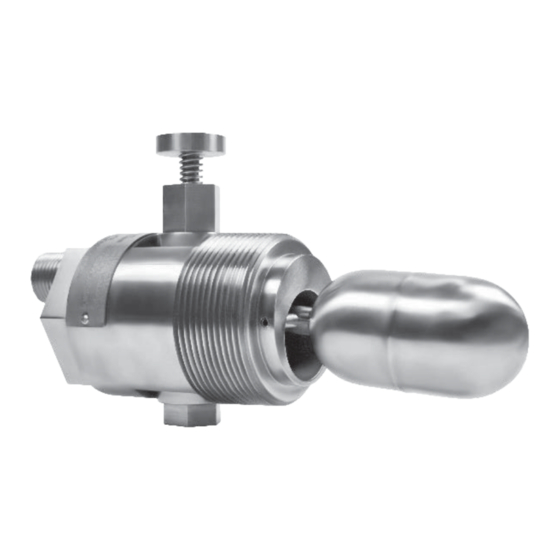
3.0 REFERENCE INFORMATION This section illustrates an overview of the L072 Side-Mounted Liquid Level Switch for CRN Installations, as well as information on troubleshooting common problems, agency approval listings, and detailed physical, functional and performance specifications. 3.1 DESCRIPTION The L072 Side-Mounted Liquid Level Switch for CRN Installations is a float-actuated device designed to be horizontally mounted within a process vessel through threaded connections. -
Page 9: Unit Causes
3.3.2 Unit Causes If a thorough inspection of any external causes fails to locate the problem, proceed to an inspection of the unit, itself. DISCONNECT POWER TO THE LEVEL SWITCH BEFORE PROCEEDING. SYMPTOM PROBLEM SOLUTION THE UNIT IS UNRESPONSIVE. ELECTRICAL FAILURE. ELECTRICAL CONTINUITY CHECKER TO DETERMINE IF THE... -
Page 10: Agency Approvals
3.4 AGENCY APPROVALS AGENCY APPROVED MODEL(S) FILE NUMBER PROTECTION AREA CLASSIFICATION L072 E203716 EXPLOSION-PROOF RECOGNIZED UNDER UL508 MOTOR CONTROLLERS L072-BBCC-DDEE 3009422 EXPLOSION-PROOF WITH ENCLOSURE: CLASS I, DIV 1; GROUPS C & D L072ABBCC-DDEE 3024568 CLASS II, DIV 1; GROUPS E, F & G 3059549 CLASS III, TYPE 4, T6 NO ENCLOSURE:... -
Page 11: Enclosure Specifications
3.5.2 Enclosure Specifications ENCLOSURE RATING NEMA 4 (OZ Gedney); NEMA 4, 7, 9 (Pyromation); NEMA 4X IP66 (Moore) Class I, Div. 1, Groups C & D ENCLOSURE MATERIAL 316/316L Stainless Steel, Cast Iron/Aluminum, or Aluminum 4” SPST OR SPDT REED SWITCH JUNCTION BOX ∕... -
Page 12: Model Configurator
3.6 MODEL CONFIGURATOR TECHNOLOGY MODEL CONFIG. MOUNTING HOUSING FLOAT ELECTRICAL & J-BOX Liquid Level Side-Mount 100 VA SPST & No Standard 1 ½” NPT 316/316L S.S. Standard 316 S.S. Sensor Level Switch J-Box Custom 2” NPT Hastelloy C276 Extended 316 S.S. 07 30 VA SPDT &... -
Page 13: Notes
3.7 NOTES L072 SIDE-MOUNTED LIQUID LEVEL FLOAT SWITCH WITH MANUAL RESET FOR CRN INSTALLATIONS... - Page 14 ASSURED QUALITY & SERVICE COST LESS Service Policy Return Material Procedure Owners of Solutions With Innovation products may In order to efficiently process any returned materials, it is request a return of the product, or any part of the product essential that a Return Material Authorization (RMA) number for complete rebuilding or replacement.
Need help?
Do you have a question about the SWI L072 and is the answer not in the manual?
Questions and answers