
Subscribe to Our Youtube Channel
Related Manuals for Ametek SWI F001


Summary of Contents for Ametek SWI F001
- Page 1 F001/F002 FLOW SWITCH INSTALLATION AND OPERATIONS MANUAL 90° Angle Flow Switch ISO 9001:2008 CERTIFIED...
- Page 2 This manual provides information on the Notice of Copyright and Limitations F001 & . It is important F002 90° Angle Flow Switches Copyright ©2022 AMETEK Magnetrol USA, LLC that all instructions are read carefully and followed All rights reserved. sequentially. QuickStart...
-
Page 3: Table Of Contents
F001/F002 FLOW SWITCH 90° Angle Switch TABLE OF CONTENTS 1.0 Quickstart Installation 1.1 Getting Started..............4 1.1.1 Equipment and Tools..........4 1.1.2 Configuration Information........4 2.0 Complete Installation 2.1 Unpacking................5 2.2 Installation Location............5 2.3 Before You Begin..............5 2.3.1 Site Preparation............5 2.3.2 Equipment and Tools..........5 2.4 Mounting................6 2.4.1 Installing the Switch............6 2.5 Wiring..................7... -
Page 4: Quickstart Installation
1.0 QUICKSTART INSTALLATION The Quickstart Installation procedures provide key steps for mounting, wiring and configuring the F001/ F002 Flow Switches. These procedures are intended for experienced installers of electronic level measurement instruments. Refer to for detailed installation instructions. Section 2.0: Complete Installation 1.1 GETTING STARTED Before beginning the Quickstart Installation procedures, have the proper equipment, tools and information readily available. -
Page 5: Complete Installation
2.0 COMPLETE INSTALLATION This section provides detailed procedures on properly installing the F001 & F002 90° Angle Flow Switches. CAUTION! IF THE EQUIPMENT IS USED IN A MANNER NOT SPECIFIED BY THE MANUFACTURER, PROTECTION PROVIDED BY THE EQUIPMENT MAY BE IMPAIRED. 2.1 UNPACKING Unpack the instrument, carefully. -
Page 6: Mounting
2.4 MOUNTING The F001 and F002 90° Angle Flow Switches are mounted using a threaded process connection. These devices are meant to be installed vertically with the inlet port facing downward. Contact the manufacturer for additional mounting options. 2.4.1 Installing the Switch WARNING! DO NOT DISASSEMBLE THE FLOW SWITCH WHEN IT IS IN SERVICE AND/OR UNDER PRESSURE. -
Page 7: Wiring
2.5 WIRING CAUTION! OBSERVE ALL APPLICABLE ELECTRICAL CODES AND PROPER WIRING PROCEDURES. 2.5.1 General Purpose Wiring • A General Purpose Installation does not have flammable media present. • Power must be shut off before attempting to wire the device. How to Install General Purpose Wiring: SPST Reed Switch: SPDT Reed Switch: Connect the wiring to the red switch... -
Page 8: Preventative Maintenance
3.0 PREVENTATIVE MAINTENANCE Periodic inspections are necessary to maintain the proper functionality of the F001/F002 Flow Switches. The switches are a safety device that protects the equipment they serve. A systematic program of preventative maintenance should be implemented at the time of installation. If the following instructions are completed routinely, the switches will provide continuous, reliable protection. -
Page 9: Reference Information
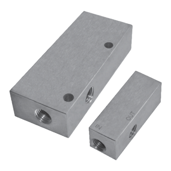
4.0 REFERENCE INFORMATION This section illustrates an overview of the F001 & F002 90° Angle Flow Switches, as well as information on troubleshooting common problems, agency approval listings, and detailed physical, functional and performance specifications. 4.1 DESCRIPTION F001 & F002 90° Angle Flow Switches are cost-effective devices installed in-line with the REED SWITCH application’s fluid movement to monitor flow rates... -
Page 10: Agency Approvals
4.4 AGENCY APPROVALS AGENCY APPROVED MODEL(S) FILE NUMBER AREA CLASSIFICATION F001 & F002 E203716 RECOGNIZED UNDER UL508 MOTOR CONTROLLERS (NKPZ2, NKPZ8) 4.5 SPECIFICATIONS CAUTION! UNITS ARE CALIBRATED TO BE MOUNTED VERTICALLY WITH THE INLET FACING DOWNWARD. FOR OTHER MOUNTING ORIENTATIONS, CONSULT THE MANUFACTURER TO HAVE UNITS CALIBRATED IN THE DESIRED ORIENTATION FOR YOUR APPLICATION. -
Page 11: Dimensional Specifications
4.5.2 Dimensional Specifications MODEL “A” DIM. “B” DIM. “C” DIM. “D” PORT SIZE NPT F001 2 ¾” ¼” 1” 1” F002 4 ⅛” 1 ¾” 1” ¼” F001 & F002 90° ANGLE FLOW SWITCH... -
Page 12: Model Configurator
4.6 MODEL CONFIGURATOR TECHNOLOGY MODEL CONFIG. PROCESS SIZE/MATERIAL SWITCH FLOW RATE* DIRECTION F Flow Switch Angled, Small Body Standard XXXX Custom Application F001 Models YYY Rate (GPM) Decreasing Angled, Large Body Custom 0201 1/4” NPT Ports (Brass) N.O. SPST (No Flow) Increasing 0208 1/4”... -
Page 13: Notes
4.7 NOTES F001 & F002 90° ANGLE FLOW SWITCH... - Page 14 ASSURED QUALITY & SERVICE COST LESS Service Policy Return Material Procedure Owners of Solutions With Innovation products may In order to efficiently process any returned materials, it is request a return of the product, or any part of the product essential that a Return Material Authorization (RMA) number for complete rebuilding or replacement.
Need help?
Do you have a question about the SWI F001 and is the answer not in the manual?
Questions and answers