Advertisement
Installation and Assembly:
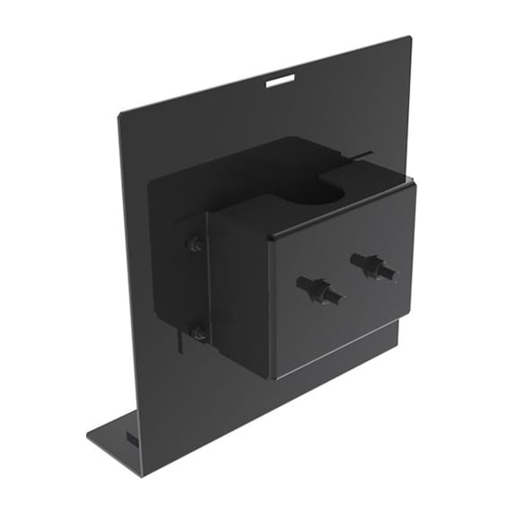
Pole PC Mount
Model: MIS488
ACC488
Note: Read entire instruction sheet before you start installation and assembly.
• Do not begin to install your Peerless product until you have read and understood the instructions and warnings
contained in this Installation Sheet. If you have any questions regarding any of the instructions or warnings, please
call Peerless customer care at 1-800-729-0307.
• This product should only be installed by a qualified professional.
• Make sure that the wall will safely support the combined load of the equipment and all attached hardware and compo-
nents.
• Never exceed the Maximum Load Capacity of 25 lb (11.3 kg).
• Always use an assistant or mechanical lifting equipment to safely lift and position equipment.
• Tighten screws firmly, but do not overtighten. Overtightening can damage the items, greatly reducing their holding
power.
2300 White Oak Circle. • Aurora, IL 60502 • (800) 729-0307 or (708) 865-8870 • Fax: (708) 865-2941 • www.peerlessmounts.com
WARNING
Max Load Capacity: 25 lb (11.3 kg)
ISSUED: 10-30-15 SHEET #: 126-9088-1
Advertisement
Table of Contents

Related Manuals for PEERLESS Mounts ACC488


Summary of Contents for PEERLESS Mounts ACC488
- Page 1 Installation and Assembly: Pole PC Mount Model: MIS488 ACC488 Max Load Capacity: 25 lb (11.3 kg) Note: Read entire instruction sheet before you start installation and assembly. WARNING • Do not begin to install your Peerless product until you have read and understood the instructions and warnings contained in this Installation Sheet.
- Page 2 Note: Read instruction sheet before you start installation and assembly. Parts List Description Qty. Part # 3/8-16 hex nut 530-9310 washer 540-9407 PC bracket 124-T1133 3/8-16 x 3.25" u-bolt 560-1060 1/4-20 nylock nut 530-9413 PC mounting bracket 124-T1134 bumper 590-1159 1/4-20 x 5/8"...
- Page 3 WARNING • Installer must verify that the supporting surface will safely support the combined weight of all attached equipment and hardware. Attach PC mounting bracket (U) to existing pole Attach six bumper strips (W) to PC bracket (Q). using four washers (N) and four hex nuts (I). EXISTING POLE Attach PC bracket (Q) to PC mounting bracket (U) using four 1/4-20 nylock nuts (T) and four 1/4-20 x 5/8"...
- Page 4 NOTE: Use safety belt (Z) instruction in conjuction with this step. Fasten clear strips to the two slots in PC bracket (Q). Set HD box into computer plate (B). Fasten belt with cinch buckle to belt without cinch buckle. Place tri-bar belt clips and belt guide onto belt as shown in the safety belt instructions.
Need help?
Do you have a question about the ACC488 and is the answer not in the manual?
Questions and answers