
Related Manuals for PKP DND01.01 Series


Summary of Contents for PKP DND01.01 Series
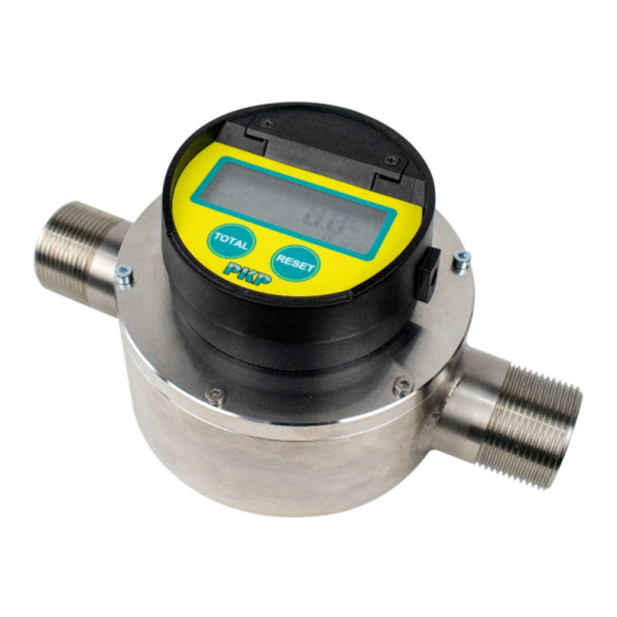
- Page 1 Instruction Manual DND01 Nutating Disc Meter PKP Prozessmesstechnik GmbH Borsigstraße 24 D-65205 Wiesbaden-Nordenstadt Tel.: ++49-(0)6122-7055-0 Fax: ++49-(0)6122-7055-50 Email: info@pkp.de www pkp.de...
-
Page 2: Table Of Contents
Table of Contents Safety Information........................2 Installation..........................3 Putting into operation......................4 Evaluation units general......................5 Electrical Connection / Evaluation units................6 Function of the on-site display.....................12 Programming of the on-site display..................14 Linearisation.........................18 Additional programming of more parameters for display with pulse and analogue output (Type B and D2)........................19 Cleaning..........................22 Safety Information... -
Page 3: Installation
Qualified Personnel The DND01 devices may only be installed by trained, qualified personnel who are able to mount the devices correctly. Qualified personnel are persons, who are familiar with assembling, installation, placing in service and operating these devices and who are suitably trained and qualified. -
Page 4: Putting Into Operation
Putting into operation As with any fine instrument, care must be taken in the installation. Your particular meter may be of special design and may require special information, however, these tips cover several points of concern with all models. Please verify the following prior to installation and operation. —... -
Page 5: Evaluation Units General
Evaluation units general Features: Large, six-digit LCD display Display in litres, pints, quarts or gallons freely programmable 11-digit non-resettable totaliser and 6-digit resettable totaliser Replaceable battery with long life Stored calibration factor 9-point linearisation ... -
Page 6: Electrical Connection / Evaluation Units
Electrical Connection / Evaluation units DND01, Code R potential free Reed contact, pulse output, 2,7 m cable: Connection plan: green white Pulse per unit of measure Model Connection Pulses/litre Pulses/Gallon DND01.01…. 3/4“ male 52,4 198,3 DND01.02…. 1“ male 52,4 198,3 DND01.03…. - Page 7 On Site Display (mounted or seperate), Pulse output NPN, Analoge output (4...20 mA), 3 m cable, order code B or Option D2 Connection plan: Register wiring External DC+ Yellow External ground Brown Pulse output White Analog output Green DC input 8 to 24 VDC;...
- Page 8 DND01, Code M NAMUR Pulse output, unscaled, 2 m cabel Technical data: Switching function Normally open (NO) Output type NAMUR 2-wire Nominal voltage Uo 8,2 V (Ri ca. 1 kΩ) Effective internal Ci ≤ 15 nF; a cable length of 10m is inductivity considered Effective...
- Page 9 Pulse per unit of measure Model Connection Pulses/litre Pulses/Gallon DND01.01…. 3/4“ male 52,4 198,3 DND01.02…. 1“ male 52,4 198,3 DND01.03…. 3/4“ male 52,4 198,3 white DND01.04…. 1“ male 52,4 198,3 DND01.05…. 3/4“ male 52,4 198,3 DND01.06…. 1“ male 52,4 198,3 DND01.08….
- Page 10 DND01, Code P or N PNP or NPN pulse output, Open Collector, unscaled, 3 m cabel Connection: white red (+) black (-) Technical data: Switching function Open collector Output type NPN or PNP 3-wire (2 versions available) Supply voltage 5-30 VDC (I ≤ 15 mA) Supply current 100 mA max ( Pmax = 0,66 watt) Effective...
- Page 11 Pulse per unit of measure Model Connection Pulses/liter Pulses/gallon DND01.01…. 3/4“ male 52,4 198,3 DND01.02…. 1“ male 52,4 198,3 DND01.03…. 3/4“ male 52,4 198,3 DND01.04…. 1“ male 52,4 198,3 DND01.05…. 3/4“ male 52,4 198,3 DND01.06…. 1“ male 52,4 198,3 DND01.08…. 1“...
-
Page 12: Function Of The On-Site Display
Function of the on-site display The register display consists of two rows of seven-segment digits, status, unit of measures, flow rate, battery indicators. Operating function settings programming are provided using the TOTAL and RESET buttons. Normal operation To enter normal operation mode - when the screen is blank after exiting programming mode, or upon initial use, press either the TOTAL or RESET button once. - Page 13 Flow rate PER MIN is displayed in conjunction with the unit of measure. All flow rates are calculated in volume unit per minute. Battery The "LBat" indicator will indicate when the battery is approaching end of life. When the indicator is illuminated, the CR123A, 3.0 VDC lithium battery is drained to 10% of its total capacity and should be changed.
-
Page 14: Programming Of The On-Site Display
Programming of the on-site display In programming mode only, pressing and releasing the TOTAL button advances to the next parameter on the current screen. Pressing and releasing the RESET button changes the current flashing selection to another selection (such as “L” to “GAL”). To enter the programming mode, press the TOTAL button three times and then press the RESET button three times (the time lag between pressing both buttons six times must be within two seconds). - Page 15 Scale factor The register collects input pulses from the oval gear meter and then determines the appropriate display output using the scale factor. This scale factor varies depending upon the viscosity of the liquid being measured, therefore calibrating the meter and register in the appropriate liquid will affect the scale factor.
- Page 16 Changing the display orientation Depending on the orientation perpendicular or inline on the meter. For remote version, this will be set to “o”. Flow direction Inline Perpendicular 1. Press the RESET button to toggle between available options (“I, for an inline-to- flow orientation and “P”...
- Page 17 Changing the display mode The display mode screen (indicated by a “d” on the top row, on the left side) determines the information displayed on the top line of the register during normal operation. The display mode may be either the totalizer screen or the flow rate screen. “C,”...
-
Page 18: Linearisation
Linearisation Indicated by 1 – 9 on the left hand side of the display, followed by a hyphen (-), this screen allows the setting of the linearisation (in total 9 points). Linearisation point 1 (of 9) Press the TOTAL button to select a digit (selected digits flash). Press RESET to change the selected digit. -
Page 19: Additional Programming Of More Parameters For Display With Pulse And Analogue Output (Type B And D2)
Additional programming of more parameters for display with pulse and analogue output (Type B and D2) Analogue minimum flow rate Indicated by a “L” on the left hand side of the display, this screen allows the setting of the flow rate that corresponds to the 4 mA output: NOTE: The minimum flow rate value must be less that the maximum flow rate value. - Page 20 Output pulse length Indicated by a “P” on the left hand side of the display, this screen allows the selection of the low duration of the output pulse. • “0” for zero milliseconds (pulse output is disabled) • “2” for 2 milliseconds •...
- Page 21 Pulse rate out Indicated by an “o” on the left hand side of the display, this screen allows selection of the pulses output per liter or per gallon depending on unit of measure (0.01 PPL/PPG to 100 PPL/PPG). The meter pulse rate is entered in pulses per liter if the selected unit of measure is liters. The meter pulse rate is entered in pulses per gallon if the selected unit of measure is gallons, quarts or pints.
-
Page 22: Cleaning
Cleaning Before cleaning, switch off the appliance and disconnect it from the mains. Clean with a damp cloth. Do not use cleaning agents. Clean parts in isopropyl alcohol, methanol (wood alcohol) or ethanol (grain alcohol). If necessary, use a nylon bristle brush, but never a wire brush! Lime deposits may be removed with a five minute soak in regular household vinegar followed by scrubbing with a nylon bristle brush. - Page 23 The number of nutating disc movements is transmitted via a magnetic coupling to the surface-mounted device. 20221011 +49 (0) 6122-7055-0 • T +49 (0) 6122 7055-50 PKP Prozessmesstechnik GmbH Subject to technical Borsigstr. 24 • D-65205 Wiesbaden info@pkp.de •...
- Page 24 NAMUR M: N/O, 2-wire, U 8,2 V (R approx.. 1 kΩ) please contact PKP. LED switching status display, Protection class: IP65 2 m cable, IP66 / IP67, -25...70 °C Additionally only for output signal B and D2:...
Need help?
Do you have a question about the DND01.01 Series and is the answer not in the manual?
Questions and answers