
Related Manuals for PKP DS09


Summary of Contents for PKP DS09
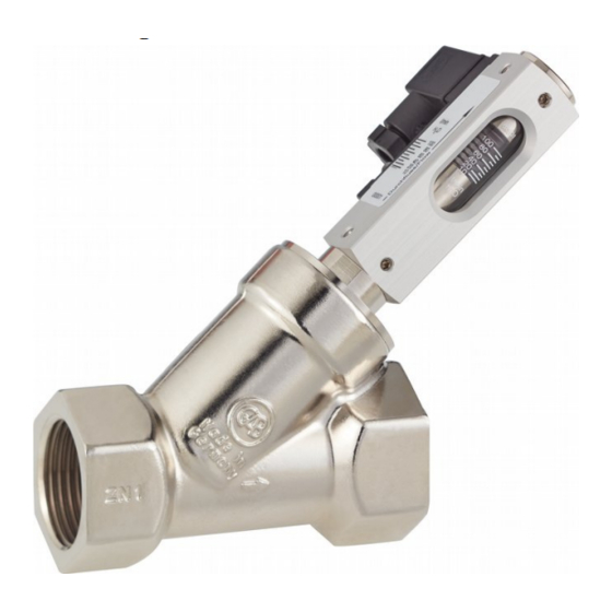
- Page 1 Instruction Manual DS09 Angle Seat Variable Area Flow Meter PKP Prozessmesstechnik GmbH Borsigstraße 24 D-65205 Wiesbaden-Nordenstadt Tel.: ++49-(0)6122-7055-0 Fax: ++49-(0)6122-7055-50 Email: info@pkp.de...
-
Page 2: Table Of Contents
The series DS09 flow meter devices should not be deployed as the sole agents to prevent dangerous conditions occurring in plant or machinery. Machinery and plant need to be designed in such a manner that faulty conditions and malfunctions do not arise that could pose a safety risk for operators. -
Page 3: Functional Description
Qualified Personnel The DS09 devices may only be installed by trained, qualified personnel who are able to mount the devices correctly. Qualified personnel are persons, who are familiar with assembling, installation, placing in service and operating these devices and who are suitably trained and qualified. -
Page 4: Design
Keep a space of minimum 100mm to those materials (e.g. steel). Ensure that there are no foreign particles in the device • Ensure that the device is not soiled • Do not use any medium containing solids • DS09 Instruction manual 05/2018 page 4... - Page 5 – Never reduce the pipe diameter immediately before the device Unimpeded flow sections An unimpeded flow section of 10xDN (rated width) must be maintained before the device. An unimpeded flow section of 5xDN (rated width) must be maintained after the device. DS09 Instruction manual 05/2018 page 5...
- Page 6 If the pipe system ends at an unimpeded outlet, the flow monitor must not be installed directly in front of the opening. The device must always be completely filled with media to ensure measuring accuracy. DS09 Instruction manual 05/2018 page 6...
-
Page 7: Installation
This may cause malfunctions. Make sure that the plant is operating without cavitation. Cavitation may result in malfuncti- • ons and damage to the device. DS09 Instruction manual 05/2018 page 7... -
Page 8: Tightening Torque
Tightening torque DS09 Instruction manual 05/2018 page 8... -
Page 9: Electrical Connection
Switch contact with connector in compliance with EN175301-803, form C Switch position under no-flow condition: Normally Open (NOC) Change Over (COC) Pin assignment plug socket (the ground-pin is not used) Normally Open (NOC) Change Over (COC) DS09 Instruction manual 05/2018 page 9... - Page 10 Change Over (COC) Pin assignment M12x1 plug connection Grounding the device When installing the device in a pipe system, ensure that the device is grounded to the pipe system to avoid a dangerous electrical potential difference. DS09 Instruction manual 05/2018 page 10...
-
Page 11: Contact Protection Measures
Lamp loads consist e.g. by light bulbs, starting motors . WARNING: High current spikes at switching on, because the glowing spiral has low resistance at low temperature. Protective measures: (examples) Limitation of current by a resistor or preheating of the glowing spiral. DS09 Instruction manual 05/2018 page 11... - Page 12 Boucherot cells may exist. For Reed switches of 10 – 40 VA Voltage [V] Resistance [Ohm] Capacitance [nF] 1500 For Reed switches of 40 – 100 VA Voltage [V] Resistance [Ohm] Capacitance [nF] 1000 DS09 Instruction manual 05/2018 page 12...
-
Page 13: Venting The Valve
3. Tighten the set screw of the switch contact, using a hex screwdriver. When doing so, ob- serve the correct tightening torque of the screw. The set switch point corresponds to the switch-off point of the switch contact by decreasing flow. DS09 Instruction manual 05/2018 page 13... -
Page 14: Checking / Reading-Off The Flow
1. The top edge of the float is the read-off point 2. To obtain greatest reading accuracy, read-off at eye level. The readoff value can be falsified by viewing at an angle 3. Read-off the flow value from the measuring scale DS09 Instruction manual 05/2018 page 14... -
Page 15: Troubleshooting Guide
Troubleshooting guide DS09 Instruction manual 05/2018 page 15... - Page 16 DS09 Instruction manual 05/2018 page 16...
- Page 17 • • • • • • •...
- Page 20 • • • • • • • • •...
Need help?
Do you have a question about the DS09 and is the answer not in the manual?
Questions and answers