Table of Contents
Advertisement
Quick Links
Advertisement
Table of Contents

Related Manuals for PKP DB50


Summary of Contents for PKP DB50
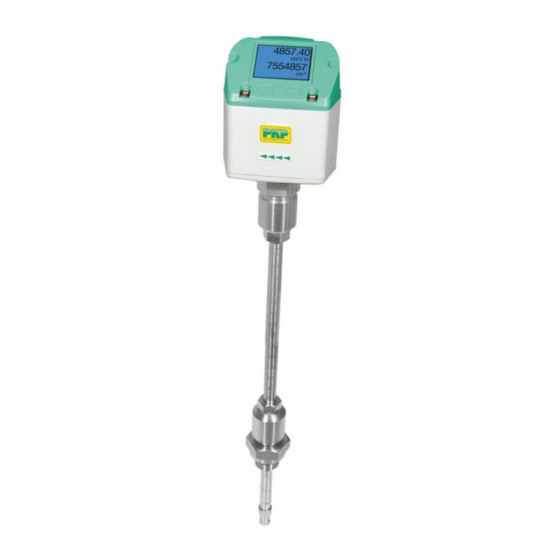
- Page 1 Instruction Manual DB50 Thermal Mass Flow Meter and Counter for compressed air and non aggressive gases PKP Prozessmesstechnik GmbH Borsigstraße 24 D-65205 Wiesbaden-Nordenstadt Tel.: ++49-(0)6122-7055-0 Fax: ++49-(0)6122-7055-50 Email: info@pkp.de...
-
Page 2: Foreword
Foreword Dear customer, thank you very much for deciding in favour of the DB50. Please read this installation and operation manual carefully before mounting and initiating the device and follow our advice. A riskless operation and a correct functioning of the DB50 are only guaranteed in case of careful observation of the described instructions and notes. -
Page 3: Table Of Contents
4.3.2 Spot drilling collar with ball valve ..................11 Installation of the Sensor ....................12 4.4.1 Mounting DB50 onto the ball valve .................. 12 Display Head Position ......................12 Measuring ranges ......................13 Maximum Flow Ranges „Low Speed“ ................14 Maximum Flow Ranges „Standard“ ................... 16 Maximum Flow ranges „Max speed“... - Page 4 Heater Error ..........................47 Internal Error ..........................47 Temp out of Range ........................47 Maintenance ......................48 Cleaning of the sensor head ..................48 Re-Calibration ......................48 Spare parts and repair ....................48 Calibration .........................48 Warranty ........................48 DB50 English V1.18 Seite 4...
-
Page 5: Safety Instructions
PKP is also not liable for consequential damage resulting from the delivery, capability or use of this device. We offer you to take back the instruments of the instruments family DB50 which you would like to dispose of. - Page 6 Water) admission, however, it can be used for natural gas. A DVGW admission is not mandatory. The consumption sensor DB50 corresponds with the latest state of technology and can generally be used for burnable and non-burnable gases. For the use in e.g. natural gas, the sensor will be calibrated in natural gas. The calibration protocol (inspection certificate) is included in the scope of delivery.
- Page 7 DB50 max. version 185 m/s, please take the flow rates from the tables on pages 16-17 DB50 high speed version 224 m/s, please take the flow rates from the tables on pages 18-19 1. DB50 with Display with 4… 20 mA analogue- and pulse output...
-
Page 8: Instruments Description
Instruments description 2 Instruments description The DB50 is a compact consumption counter for compressed air and gases. Special features: - Optimum accuracy due to compact design - Intgrated Display showing Flow, consuption, velocity and temperature - Input inner tube diameter via display keys - Units free selectable. -
Page 9: Technical Data
± 1,5 % m.v.*, ± 0,3 % f.s.* Display: optional TFT 1.8“ Resolution 220 x 176 Mounting thread: G ½“, optional ½” NPT Material: Stainless steel 1.4301 / 1.4404 Protection class IP65 ‘* m.v. = measured values f.s. = full scale DB50 English V1.18 Seite 9... -
Page 10: Installation
5 x D The values represent the min. lengths. In case the min. inlet / outlet runs could not be ensured, it must be expected to get increased or significant deviations of the measurement values. DB50 English V1.18 Seite 10... -
Page 11: Installation Db50
4.3.2 Spot drilling collar with ball valve In case the system could not be shut down, means to be set depressurized, there could be used the optional spot drilling collar and drilling jig to drill through the ball valve. DB50 English V1.18 Seite 11... -
Page 12: Installation Of The Sensor
Installation Installation of the Sensor 4.4.1 Mounting DB50 onto the ball valve Assembly is carried out by inserting the connection thread with gasket. (G1/2“ thread, SW 32) into the ball valve with ½"internal thread. The sensor has be tighten by hand as far as possible and then tighten with stipulated torque of 25-30 Nm. -
Page 13: Measuring Ranges
For the use in e.g. natural gas, the sensor will be calibrated in natural gas. The calibration protocol (inspection certificate) is included in the scope of delivery. The area outside the pipe (environment of the sensor) is not allowed to be an explosive area. (Ex area) . DB50 English V1.18 Seite 13... -
Page 14: Maximum Flow Ranges „Low Speed
383,8 652,5 413,0 383,8 397,9 409,3 247,0 64,2 479,5 441,0 749,8 474,6 441,0 457,2 470,3 283,8 Referred to DIN 1945 / ISO 1217 (20°C, 1000mbar) and compressed air. Referred to DIN 1343: 0°C, 1013,25 mbar DB50 English V1.18 Seite 14... - Page 15 88454,9 150390,8 95189,7 88454,9 91706,5 94341,5 56920,6 1000,0 118752,2 109203,6 185667,6 117518,1 109203,6 113217,9 116471,0 70272,3 Referred to DIN 1945 / ISO 1217 (20°C, 1000mbar) and compressed air. Referred to DIN 1343: 0°C, 1013,25 mbar DB50 English V1.18 Seite 15...
-
Page 16: Maximum Flow Ranges „Standard
765,6 711,5 736,8 758,9 457,9 92,7 64,2 889,1 817,6 1390,0 879,8 817,6 846,7 872,0 526,1 92,7 Referred to DIN 1945 / ISO 1217 (20°C, 1000mbar) and compressed air. Referred to DIN 1343: 0°C, 1013,25 mbar DB50 English V1.18 Seite 16... - Page 17 176468,9 163995,2 169831,2 174909,1 105530,6 92,7 1000,0 220166,6 202463,2 344215,1 217862,8 202463,2 209668,2 215937,1 130284,7 92,7 Referred to DIN 1945 / ISO 1217 (20°C, 1000mbar) and compressed air. Referred to DIN 1343: 0°C, 1013,25 mbar DB50 English V1.18 Seite 17...
-
Page 18: Maximum Flow Ranges „Max Speed
1528,1 1420,0 1472,2 1514,5 913,7 185,0 64,2 1774,3 1631,7 2774,1 1755,9 1631,7 1691,6 1740,2 1050,0 185,0 Referred to DIN 1945 / ISO 1217 (20°C, 1000mbar) and compressed air. Referred to DIN 1343: 0°C, 1013,25 mbar DB50 English V1.18 Seite 18... - Page 19 352202,1 327282,7 339313,7 349063,4 210605,9 185,0 1000,0 439383,1 404052,7 686970,6 434817,4 404052,7 418905,8 430942,5 260007,2 185,0 Referred to DIN 1945 / ISO 1217 (20°C, 1000mbar) and compressed air. Referred to DIN 1343: 0°C, 1013,25 mbar DB50 English V1.18 Seite 19...
-
Page 20: Maximum Flow Ranges „High Speed
1850,2 1719,3 1782,5 1833,7 1106,4 224,0 64,2 2148,4 1975,6 3359,0 2126,1 1975,6 2048,3 2107,1 1271,3 224,0 Referred to DIN 1945 / ISO 1217 (20°C, 1000mbar) and compressed air. Referred to DIN 1343: 0°C, 1013,25 mbar DB50 English V1.18 Seite 20... - Page 21 426450,0 396278,4 410844,6 422649,7 255003,8 224,0 1000,0 532009,9 489231,3 831791,3 526481,5 489232,6 507215,6 521789,8 314819,5 224,0 Referred to DIN 1945 / ISO 1217 (20°C, 1000mbar) and compressed air. Referred to DIN 1343: 0°C, 1013,25 mbar DB50 English V1.18 Seite 21...
-
Page 22: Dimension
Dimension 6 Dimension 416,0 (Standard Schaft 220mm) SW 27 SW 32 220 mm(Standard) Optional: 120, 160, 300, 400 mm Connector plug A Connector plug B DB50 English V1.18 Seite 22... -
Page 23: Electrical Wiring
DIP Switch to “On”. It must be ensured that the connection plugs are still plugged and the gasket is installed correctly. Alternatively, a 120R resistor can be installed in the plug between pin 2 and pin DB50 English V1.18 Seite 23... -
Page 24: Ethernet (Optional Poe)
- Connector plug B (M12 X-coded 8 pole) Connector plug B Connection cable M12 x-coded 8 pole M12 x-coded to RJ45 Data LINES: 1,2 und 3,4 PoE LINES: 5,6 und 7,8 M12 x 1 Connection cable: Cat 6. *PoE: Power over Ethernet DB50 English V1.18 Seite 24... -
Page 25: Operation
Operation Remark: In version with display only. “OK“ ( ) “Up“ ( The operation of the DB50 is done by the two capacitive key buttons Up ( ) und Enter ( DB50 English V1.18 Seite 25... -
Page 26: Initialization
Operation 8.1 Initialization After switching on the DB50, the initialized screen is displayed followed by the main menu. Main menu *** *** Gas / Status Info HW Version Modbus ID Page-No. SW Version Switching to pages 2-4 or back by pressing key „... -
Page 27: Settings
Selection of a menu item or to change a value is done with the key “, a final move to the „ chosen menu item or takeover of the value change needs the confirmation by pressing the „OK“ DB50 English V1.18 Seite 27... -
Page 28: Sensor Setup
, select the respective position „“ and activate the position with the "OK" button. By pressing the position value is „“ incremented by 1. Complete with "OK" activate next number position. Confirm entry by pressing „OK“. DB50 English V1.18 Seite 28... -
Page 29: Input / Change Consumption Counter
In case the quantity of units selectable are not presentable on one page, pleas move to next page by pressing „<<“ Confirm selection by pressing 2x „OK“. Procedure for all 4 measurement variables is analogous. DB50 English V1.18 Seite 29... -
Page 30: Definition Of The Reference Conditions
1. Complete with "OK" activate next number position. Procedure for changing the reference temperature is the same. Setup Sensor Setup Advanced Filtertime DB50 English V1.18 Seite 30 Under point together with the "Filtertime" appropriate an attenuation can "Filter Grade"... - Page 31 Input values of 0 -10000 in [ms] are possible Setup Sensor Setup Advanced AV-Time The time period for averaging can be entered here. Input values of 1-1440 [minutes] are possible. For average values see display window 3 + 4 DB50 English V1.18 Seite 31...
-
Page 32: Setting Of Zeropoint And Low-Flow Cut Off
Setup Sensor Setup ZP Adjust t Reset By selection of all settings for „Reset“ and. „CutOff“ are reset. „ZeroPnt“ 1,03 Menu item to be select with button „“ confirm the reset with „OK“ Leave menu with button „Back“ DB50 English V1.18 Seite 32... -
Page 33: Modbus Settings
Operation 8.3.2 Modbus Settings 8.3.2.1 Modbus RTU Setup The Flow sensors DB50 comes with a Modbus RTU Interface. Before commissioning the sensor the communication parameters Modbus ID, Baudrate, Parity und Stop bit must be set in order to ensure the communication with the Modbus master. -
Page 34: Modbus Tcp (Optional)
Operation 8.3.2.2 Modbus TCP (Optional) The Flow sensors DB50 comes optional with a Modbus TCP Interface (HW Interface:M12 x 1 X-coded connector). Device supports with this option the Modbus TCP protocol for communication with SCADA systems. TCP port is set to 502 by default. Port can be changed at the sensor or using PC Service Software Modbus device address (Unit Identifier) can be set in the range of 1- 255. -
Page 35: Network Settings Static Ip
Select the desired position with the key and ">" activate it with the key. "OK" Change the values with the key, and accept ">" the values with the key. "OK" Procedure for "Subnet" "Gateway" analogous. Store the settings by „Save“ DB50 English V1.18 Seite 35... -
Page 36: Modbus Tcp Settings
(Little Endian) and "ABCD" (Middle Endian) "CDAB" Saving the changes by pressing "Save", therefore select it with key and then confirm „>“ it with "OK". Reset to the default settings by activating "Set to Default"- DB50 English V1.18 Seite 36... -
Page 37: Modbus Settings Register (2001
Flow in cfm 1181 1180 Float Flow in Ncfm 1189 1188 Float 1197 1196 Float Flow in kg/h Flow in kg/min 1205 1204 Float Flow in kg/s 1213 1212 Float Flow in kW 1221 1220 Float DB50 English V1.18 Seite 37... - Page 38 GasTemp °F Remark: For DS400 / DS 500 / Handheld devices - Modbus Sensor Datatype „ Data Type R4-32“ match with „Data Type Float“ For more additional Modbus values please refer to VA5xx_Modbus_RTU_Slave_Installation_1.04_EN.doc DB50 English V1.18 Seite 38...
-
Page 39: Pulse /Alarm
1 m³ / Pulse 180000 3000 3000000 Table 1 Maximum flow for pulse output Entering pulse values that are not allow a presentation to the full scale value, are not allowed. Entries are discarded and error message displayed. DB50 English V1.18 Seite 39... -
Page 40: User Setup
0000 (4 times zero). 8.3.4.2 Language Settings UserSetup Language Currently 4 languages have been implemented and could be selected with button „“. Change of language by confirming with “OK”. Leaving the menu with button “back”. DB50 English V1.18 Seite 40... -
Page 41: Display / Touch
10s. To do this, use the button to enter the operating menu during "OK" this period 8.3.5 Advanced Settings Advanced By pressing the sensor is set „Factory Reset“ back to the factory settings. DB50 English V1.18 Seite 41... -
Page 42: -20Ma
„“ „OK“ Settings 4-20mA Channel 1 The 4-20 mA Analogue output of the Sensor DB50 can be individually adjusted. It is possible to assign following values „Temperature“, to the channel CH 1. „Velocity“ und „Flow“... - Page 43 To make changes first select a menu item "Current Error" with button and then select by pressing the „“ „OK“ the desired mode For saving the changes done press button „Save“ discard the changes press button “Cancel”. Leaving the menu with „Back“. DB50 English V1.18 Seite 43...
-
Page 44: Db50 Info
Operation 8.3.7 DB50 Info Setup Sensor Setup Info Here you get a brief description of the sensor data incl. the calibration data. 92,7 m/s 600m³/h Under you are able to see in addition the Details, calibration conditions. Run Time:... -
Page 45: Mbus
Both addresses, Primary address and ID, could be automatic searched in the M-Bus system. 8.4.2 Default values transmitted Value 1 with [Unit]*: Consumption [m³] Value 2 with [Unit]*: Flow [m³/h] Value 3 with [Unit]*: Gas temperature [°C] *All Values could be changed / preset in production DB50 English V1.18 Seite 45... -
Page 46: Status / Error Messages
Note: The measurement will continue without interruption or restriction. Direction When used in conjunction with a direction switch, the status message "Direction" is displayed in case of opposite flow direction and no measurement may take place. Status messages: Direction DB50 English V1.18 Seite 46... -
Page 47: Error Messages
Error messages: *** VA 520 *** *** VA 520 *** Low Voltage Heater Error *** VA 520 *** *** VA 520 *** Internal Error Temp out of Range *** VA 520 *** Low Voltage 4.20mA DB50 English V1.18 Seite 47... -
Page 48: Maintenance
The warranty time for the DB50 is 12 months. If no other definitions are given the accessory parts have a warranty time of 6 months. Warranty services do not extend the warranty time. - Page 49 • zero balance possible at instrument Description: Typical applications: Model DB50 thermal mass flow meters and counters report Model DB50 thermal mass flow meters and counters provide and measure mass flow rates and totals of non-aggressive flow measurement of non-aggressive gases in DN 25 to gases, regardless of gas pressure and temperature.
- Page 50 DB50.S… standard-model, mass flow rate inal [Nm³/h] 0…92,7 m/s, G 1/2 male thread pipe Natural size** DB50.H1… mass flow rate 0…185 m/s, G 1/2 male thread DN 25 DB50.H2… mass flow rate 0…224 m/s, G 1/2 male thread DN 32 Measuring ranges:...
- Page 51 Polycarbonate Material: st. st. 1.4301, Connection plug A: Electrical protection: IP 65 Dimensions: Connection plug B (pulse output / MBus): PKP Prozessmesstechnik GmbH +49 (0) 6122-7055-0 • T +49 (0) 6122 7055-50 Borsigstr. 24 • D-65205 Wiesbaden info@pkp.de • www.pkp.de...
- Page 52 ½" ball valve made of stainless steel DB50-Z.N1: wall mounted power supply, 100-240 VAC, 10 VA on 24 VDC, 0,35 A DB50-Z.N2: plug-in power supply unit, 100-240 VAC on 24 VDC, 0,35 A, with 2 m cable DB50-Z.K5: factory calibration, 5 points Order number: SM12.
Need help?
Do you have a question about the DB50 and is the answer not in the manual?
Questions and answers