Table of Contents

Related Manuals for PKP DS04.1


Summary of Contents for PKP DS04.1
- Page 1 Instruction Manual DS04 All Metal Variable Area Flowmeter and Switch - High Pressure Version - PKP Prozessmesstechnik GmbH Borsigstraße 24 D-65205 Wiesbaden-Nordenstadt Tel.: ++49-(0)6122-7055-0 Fax: ++49-(0)6122-7055-50 Email: info@pkp.de...
-
Page 2: Table Of Contents
Table of Contents Safety Information........................2 Overview..........................3 Installation..........................4 Connecting devices equipped with Reed switches..............6 Electrical connection......................8 Setting the switch point......................11 Troubleshooting guide......................12 Maintenance / Maintenance plan..................13 Degree of protection (IP-Code)....................13 Returns..........................13 Safety Information General Instructions To ensure safe operation, the device should only be operated according to the specifica - tions in the instruction manual. -
Page 3: Overview
The series DS04 flow meter devices should not be deployed as the sole agents to prevent dangerous conditions occurring in plant or machinery. Machinery and plant need to be designed in such a manner that faulty conditions and malfunctions do not arise that could pose a safety risk for operators. -
Page 4: Installation
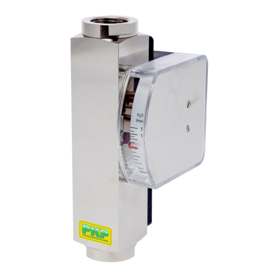
Switch point adjustment scale: A scale is applied to the device body, to which the desired switch point can be adjusted. Display scale: On the device, a display housing is mounted with integrated indicator scale and pointer movement. The pointer on the scale indicates the current flow value. - Page 5 This may result in serious injury to the user. if the mediums is contaminated by solids, a strainer must be installed before the device (e.g. SF00 or SF01 from PKP) Direction of flow: Only install the flow monitor in one of the positions displayed in the drawing. The medium must flow in the direction of the arrow (from a low to a high scale value).
-
Page 6: Connecting Devices Equipped With Reed Switches
Connecting devices equipped with Reed switches Reed switches are basically designed for small contact ratings. To connect a load with higher power consumption it is indispensable to use a contact protection relay (e.g. our series MSR01) If you connect directly a load to a Reed contact the following recommendations should be considered. - Page 7 Lamp Load Lamp loads consist e.g. by light bulbs, starting motors . WARNING: High current spikes at switching on, because the glowing spiral has low resistance at low temperature. Protective measures: (examples) Limitation of current by a resistor or preheating of the glowing spiral.
-
Page 8: Electrical Connection
Switching capacity* Type Size Contact function Angle plug IP65 M12x1 plug IP67 cable connection (1 m) IP67 DS04.1 1/4“ 1 = N/O 250 V / 3 A / 100 VA DS04.1A 3/8“ 2 = SPDT 250 V / 1,5 A / 50 VA, min. load: 3 VA DS04.2... - Page 9 Switching contact with connector acc. to EN 175301-803: Normally Open (NOC) Change Over (COC) Switch position under no-flow condition Switch position under no-flow condition The ground-pin is not used The ground-pin is not used DS04 Instruction manual 03/2020 page 9...
- Page 10 Switching contacts with plug connector M12x1 (mating connector not included in delivery) Normally Open (NOC) Change Over (COC) Switch position under no-flow condition Switch position under no-flow condition Switching contact with cable: The individual cores of the cable are numbered according to the following connection dia - gram: Normally Open (NOC) Change Over (COC)
-
Page 11: Setting The Switch Point
Setting the switch point The following instructions describe the procedure for a Normally Open Contact (NOC). The actual state (open or closed), can be determined using a continuity meter. 1. Loosen the switch contact set screws (1) using a screwdriver 2. -
Page 12: Troubleshooting Guide
Incorrect reduction fitting or Correct pipe diameter pipe diameter is too small Device is dirty Disassemble and clean the device Device is defective Remove device from system and contact PKP DS04 Instruction manual 03/2020 page 12... -
Page 13: Maintenance / Maintenance Plan
Degree of protection connection material EN 175301-803 with gland Ø of connection cable: IP65 6-8 mm M12x1 Plug connector M12x1 IP67 Cable IP67 Returns For returns please contact us: PKP Prozessmesstechnik GmbH Info@pkp.de +49 (0) 6122-7055-0 DS04 Instruction manual 03/2020 page 13... - Page 14 This ensures a bistable switch function at any time. The Reed contact is adjustable over the full measuring and switching range of the meter. 20200302 PKP Prozessmesstechnik GmbH +49 (0) 6122-7055-0 • T +49 (0) 6122 7055-50 Borsigstr. 24 • D-65205 Wiesbaden info@pkp.de •...
- Page 15 2 = for air (at 1 bar abs., 20 °C) Measuring ranges: Max. media- Water temperature: 100 °C for liquids (optional 160 °C) DS04.1, DS04.1A and DS04.2: 80 °C for gases, WA01 = 0,1–1,5 l/min LA01 = 1–28 Nl/min Ex-devices acc. to. ATEX-marking WA02 = 0,2 –3 l/min LA02 = 4–60 Nl/min...
- Page 16 ATEX II 2 G Ex mb II T5 & ATEX II 2 D Ex tD A21 IP67 T100 °C (with cable connection, Standard 2 m only) PKP Prozessmesstechnik GmbH +49 (0) 6122-7055-0 • T +49 (0) 6122 7055-50 Borsigstr. 24 • D-65205 Wiesbaden info@pkp.de •...
- Page 17 Please note that the switch-on points are higher due to the hysteresis. For applications where pressure surges are to be expected, please contact PKP! • Dirt traps SF00, SF01 • Protection relay MSR01 • M12 Plug connector PVC-cable SM12 PKP Prozessmesstechnik GmbH +49 (0) 6122-7055-0 •...
Need help?
Do you have a question about the DS04.1 and is the answer not in the manual?
Questions and answers