
Related Manuals for Q-Lab Q-SUN Xe-3 Series


Summary of Contents for Q-Lab Q-SUN Xe-3 Series
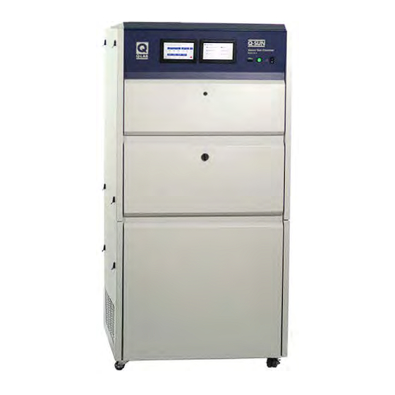
- Page 1 Q-SUN Xe-3 Q-SUN Xe-3 Xenon Test Chambers Xenon Test Chambers For Models: X3HDSE X3HCE X3HBSCE X3HSE X3HDSCE X3HSCE X3HDSBSE X3HBSE X3HDSBSCE Revision Date 11 Apr 2022...
-
Page 2: Table Of Contents
Table of Contents Table of Contents 1. Specifications, Classifications, Symbols (Feb 2015) .... 3 2. Safety Information ..............5 2.1 Heat and Electrical Shock Hazards (Dec 2020) ....5 2.2 Ultraviolet and Infrared Hazards (Mar 2019) ......7 2.3 Dual Spray System (Oct 2020) ..........8 3. -
Page 3: Specifications, Classifications, Symbols (Feb 2015)
Section 1. Specifications, Classifications, Symbols 1. Specifications, Classifications, Symbols (Feb 2015) Specifications, Classifications ● The recommended ambient operating temperature and relative humidity (RH) for the Q-SUN tester is 23 ± 5 °C and 50 ± 25% RH. ● The maximum ambient operating temperature and humidity is 40 °C and 80% relative humidity. ●... - Page 4 Section 1. Specifications, Classifications, Symbols Symbols Electrical Shock Hazard Hot Surfaces Hazard Attention Finger/Hand Crushing hazard Local Waste & recycling regulations per the WEEE Directive 2002/96/EC on Waste Electrical and Electronic Equipment...
-
Page 5: Safety Information
2. Safety Information Q-Lab accepts no responsibility for the consequences if the user fails to comply with the instructions in this operating manual. Q-Lab will accept responsibility for defective parts or components only if the machinery was defective at the time that the tester was shipped. - Page 6 Section 2. Safety Information All Q-SUN models are equipped with an interlock switch (Figure 2.1d) that turns off the xenon lamps when the lamp access door is opened. Figure 2.1d: Lamp Door Interlock Switch Location CAUTION: The vapor hose and the humidifier are hot.
-
Page 7: Ultraviolet And Infrared Hazards (Mar 2019)
Section 2. Safety Information 2.2 Ultraviolet and Infrared Hazards (Mar 2019) The Q-SUN lamps produce UV light that can cause severe sunburn, eye inflammation, and damage to your vision. Do not defeat the switch that turns off lamps when the chamber door is open. Figure 2.2 below shows the location of the chamber door interlock switch inside the right side top access panel. -
Page 8: Dual Spray System (Oct 2020)
Section 2. Safety Information 2.3 Dual Spray System (Oct 2020) Overview ● Q-SUN Xe-3 models equipped with dual spray (DS) have a separate assembly, which includes the fluid reservoir and an enclosure housing an electrically operated pump system (Figure 2.3). Electrical Shock Hazards ●... -
Page 9: General Description (Oct 2020)
Section 3. General Description 3. General Description (Oct 2020) Overview ● The LX-5080-QS Q-SUN Xe-3 Quick Setup Guide is not a technical manual. ● This guide provides basic information on uncrating and setting up Q-SUN Xe-3 Xenon Test Chambers. ● A Q-SUN Xe-3 Technical Manual is necessary for a complete understanding of how to operate Q-SUN Xe-3 Xenon Test Chambers. - Page 10 Section 3. General Description Partial List of Standard Test Methods Met by Q-SUN Xe-3 Xenon Test Chambers ● Listed below are several widely used standards that can be performed with Q-SUN Xe-3 testers. ● For an extensive list of standards Q-SUN testers can perform see LX-5054 Standards Met by Q-SUN Testers.
-
Page 11: Operating Environment
● Operating outside the recommended range can result in the tester producing chamber temperature and/or humidity faults. ● Never operate your tester in lab temperatures >40 °C or >80% RH. ● Consult with Q-Lab for more specific information about achievable chamber temperature/humidity values based upon various ambient lab conditions. Physical Environment ●... -
Page 12: Unsuitable Environments (May 2020)
Section 4. Operating Environment 4.2 Unsuitable Environments (May 2020) Salt Fog or Other Airborne Contamination ● Operating a Q-SUN tester in an unsuitable environment will void the warranty. ● DO NOT install Q-SUN testers in a room with corrosion chambers (Figure 4.2a). - Page 13 ● Low Voltage: Recurring “brown-outs” or voltages less than 90% of the rated voltage will damage electrical components. ● Water Leaks from Ceiling: Water leaking onto the tester will damage electrical components. For further detail on laboratory environment requirements, please contact Q-Lab Repair and Tester Support. See for contact information. Section 7...
-
Page 14: Setup
Section 5. Setup 5. Setup 5.1 Xe-3 Uncrating (Dec 2020) Carefully read these instructions before uncrating the tester. Follow all local, OSHA, EHS, and other applicable equipment operation and material handling safety requirements, recommendations, and practices. ● Q-SUN Xe-3 Testers are shipped in one of two types of crates (Figure 5.1a Figure 5.1b). - Page 15 Section 5. Setup Weights Shipping Weight (Approximate) Main Unit On Skid With Wooden Crate 363 kg (800 lbs) On Skid With Carton Only 318 kg (700 lbs) Tester Weight* 190-233 kg (420-512 lbs) * Weight varies based on installed options. Tools Required Phillips Screwdriver (Wooden Crate Only) Flat Blade Screwdriver...
- Page 16 Section 5. Setup Use Fork Lift to Or Use Pry Remove Crate Bar to Remove in One Piece Crate in Pieces If a fork lift is not available, use a pry bar to carefully If a fork lift is available, use it to carefully lift the remove the horizontal and vertical wooden pieces wooden frame up and off of the tester.
- Page 17 Section 5. Setup Remove Remove Remove Remove and Save X2 12. Remove the four (4) corner protectors and all Remove the exhaust vent stack pieces (X-6971) bubble wrap and tape from around the tester. and set aside. Open Remove 13. Locate the two (2) latches in the right side lower 14.
- Page 18 Section 5. Setup a. Begin by tilting the Q-SUN and removing the three foam strips under the bottom of the unit. b. “ Walk” the Q-SUN off the skid in the direction parallel to the boards of the skid. c. Slide the Q-SUN into place and adjust the leveling feet so the unit is level.
-
Page 19: Chiller Uncrating (Apr 2021)
Section 5. Setup 5.2 Chiller Uncrating (Apr 2021) ● For Q-SUN Xe-3 models with chiller (C), follow the instructions in this section to uncrate the chiller unit. ● Carefully read these instructions before uncrating the chiller. ● The tables below list chiller weights and tools needed for uncrating. ●... - Page 20 Section 5. Setup Crate with Carton and Go To Step 2 Wooden Frame Fasteners in Back Crate with Go To Step 5 Carton Only Fasteners in Front For crate with wooden frame continue with Step 2. Remove the fasteners in the bottom front and back For crate with carton only, go to Step 5.
- Page 21 Section 5. Setup Remove Remove Chiller Unit Remove the hose and bag of fittings from the top of Remove the inner carton from on top of the main the inner carton. Set aside. chiller unit. Set aside. Contents of Carton: X-6916-X CHILLER Q-SUN DUCT ASSEMBLY X-6951-X CHILLER TRANSITION DUCT ASSEMBLY X-6964-X CHILLER DUCT ASSEMBLY...
- Page 22 Section 5. Setup Remove Wrap 13. Remove any remaining plastic wrap from the chiller 14. Open the chiller front access door. unit. Remove 15. Remove the air bag from the chiller. Close the 16. Locate the four (4) screws that secure the wooden access door.
- Page 23 Section 5. Setup Slide Chiller Forward 100 mm Off Skid 20. Partially slide the unit off the skid in the direction 19. Two persons tilt the chiller. Pull the foam pieces out parallel to the boards of the skid, so that the unit from under the bottom of the unit.
- Page 24 Section 5. Setup 25. Tilt up one side of the chiller and remove the 26. Tilt up the other side of the chiller and remove the runner. Discard runner. other runner. Discard runner. Xe-3 Chiller Leveling Glides 28. If the chiller is moved, do not hit floor drain, cracks, Slide the unit into position, at the right side of the installed Xe-3.
-
Page 25: Chiller Assembly (Apr 2021)
Section 5. Setup 5.3 Chiller Assembly (Apr 2021) ● If the Q-SUN tester does not have the chiller option go to Section 5.4. ● Using six of the enclosed #6 screws, attach the Chiller Duct to the rear of the chiller (Step 3 through Step... - Page 26 Section 5. Setup Xe-3 Rear Panel Chiller Duct Opening Locate the chiller duct opening at the lower left rear Locate the chiller Q-SUN duct assembly (6916-X). of the Xe-3 rear panel. Remove ×2 Chiller Install X2 Shroud Remove ×2 Remove the tester right side lower access panel. Remove the chiller shroud in front of the air filter Using two (2) Phillips screws, loosely attach the (two screws at top and two screws at bottom of...
- Page 27 Section 5. Setup Transition Duct 12. Four (4) screw locations to attach the transition duct Locate the transition duct (X-6951-X). to the Q-SUN duct. Chiller Xe-3 Rear Drain Hose Floor Drain Locate the 1/2" drain hose at the bottom rear of the 13.
- Page 28 Section 5. Setup Align Chiller Duct Latch Foam Seal Transition Duct Transition Duct Chiller Duct Position the chiller so that the chiller duct aligns 18. Push the ducts together. Make sure the foam seal is vertically and horizontally with the transition duct. If in place.
-
Page 29: Xe-3 Exhaust Vent Assembly (Dec 2020)
Section 5. Setup 5.4 Xe-3 Exhaust Vent Assembly (Dec 2020) An exhaust vent must be installed on all Xe-3 testers. Parts of the vent assembly are shipped in a separate carton. The vent extension stack pieces are taped to the corners of the tester as shown in Section 5.1, Step Exhaust Vent Parts... - Page 30 Section 5. Setup a. Use downward pressure on the vent transition to clear the vent opening gasket and avoid tearing it. b. The mounting angles will fit against the back panel when the vent transition is fully in place. c. With the vent transition in place reach down inside and run your fingers along the edges to make sure that the vent gasket was not moved from its original position.
- Page 31 Section 5. Setup Vent Stack Bottom of Vent Stack Notched Corners Transition 12. Insert the end of the vent stack with the notched Orient the vent stack with the notched corners at corners down into the opening of the vent transition. the bottom.
-
Page 32: Back Spray Set Up (Oct 2020)
Section 5. Setup 5.5 Back Spray Set Up (Oct 2020) For Q-SUN Xe-3 models with back spray (BS), follow the instructions in Section 5.1 Section 5.4 to uncrate the Xe-3 and assemble the Xe-3 exhaust vent. Follow the instructions below to place the Back Spray manifold in the operational position. -
Page 33: Dual Spray Uncrating And Assembly (Dec 2020)
Section 5. Setup 5.6 Dual Spray Uncrating and Assembly (Dec 2020) For Q-SUN Xe-3 models with Dual Spray (DS), follow the instructions in Section 5.1 Section 5.4 to uncrate the Xe-3 and assemble the Xe-3 exhaust vent. Follow the instructions below to uncrate and assemble the Dual Spray system. Uncrating ●... - Page 34 Section 5. Setup Assembly Carefully unwrap the two (2) cart side panels (X-10081), the cart front panel (X-10082), and the cart rear panel (X-10083). The two (2) cart side panels mount on the sides of the cart (Figure 5.6e). • Install the panels by hooking the long flange under the bottom edge of the lower shelf on the cart •...
- Page 35 Section 5. Setup Front View Front Panel Figure 5.6h: Position the Dual Spray assembly next to Figure 5.6g: Install front panel. Xe-3 as shown. Power Connnector Figure 5.6j: Dual Spray power connector location on Xe-3 Figure 5.6i: Connect power cord at rear of cart. rear panel.
-
Page 36: Dimensions And Space Requirements (Mar 2020)
Section 5. Setup 5.7 Dimensions and Space Requirements (Mar 2020) All Xe-3 Models ● The Xe-3 should be positioned as shown in Figure 5.7a below. ● This position will allow sufficient room to operate the unit, gain access to service areas, and allow proper ventilation through the air intake and exhaust vents. - Page 37 Section 5. Setup Xe-3 with Chiller ● An Xe-3 with Chiller should be positioned as shown in Figure 5.7b below. ● This position will allow sufficient room to operate the unit, gain access to service areas, and allow proper ventilation through the air intake and exhaust vents.
-
Page 38: Electrical (Apr 2022)
Section 5. Setup 5.8 Electrical (Apr 2022) Specifications Voltage: All Models 208 V or 230 V or 400 V ± 10% - three phase Current: Xe-3-HSE/HBSE/HDSE/HDSBSE 39 A @ 208 V, 39 A @ 230 V, 26 A @ 400 V Xe-3-HCE/HSCE/HBSCE/HDSCE/HDSBSCE 44 A @ 208 V, 44 A @ 230 V, 26 A @ 400 V Frequency: All Models... - Page 39 Section 5. Setup Use a flat blade screwdriver to open the four (4) latches. Remove Figure 5.8c: Remove upper right side access panel to see the electrical panel. Ground (Earth) Figure 5.8d: Electrical input connections for 208 V and 230 V testers. Neutral L1 L2 L3 Must Be...
- Page 40 Section 5. Setup Chiller ● If the Xe-3 is equipped with a chiller (C models), the chiller gets power from an outlet on the Xe-3 rear panel (Figure 5.8h). Chiller Power Outlet Figure 5.8h: Power outlet for chiller on Xe-3 rear panel. Back Spray ●...
-
Page 41: Water (Sep 2020)
Section 5. Setup 5.9 Water (Sep 2020) Overview ● Purified water must be supplied to all Q-SUN Xe-3 testers. ● Water is used by the humidifier to produce humidity. ● Water is also used to spray on the test specimens in Xe-3 models with water spray. ●... - Page 42 Section 5. Setup ● Figure 5.9a below shows an effective Reverse Osmosis / Deionized Water System with Anion Type I Resin for spray water silica removal. ● For information on water purification systems, contact the Life Science business of Merck KGaA, Darmstadt, Germany. The Life Science business of Merck KGaA, Darmstadt, Germany operates as MilliporeSigma in the USA and Canada.
- Page 43 Section 5. Setup Connections ● The water supply and drain connections are made at the lower rear of the tester (Figure 5.9b). ● The Q-SUN tester is supplied with kit X-7654-K (Figure 5.9b) which includes water inlet and drain fittings to meet various connection configurations (Figure 5.9d through...
- Page 44 ● Alternatively, an optional lift kit can be used to raise the entire tester up off of the floor (see Section 14.2). ● Do not use concrete blocks, pallets, bricks, or other means to raise the tester to achieve proper drainage. ● Contact Q-Lab Repair and Tester Support with any questions about tester drainage requirements.
- Page 45 Section 5. Setup Chiller ● The chiller does not require an input water supply. ● A drain connection must be made to drain water that condenses on the chiller evaporator coil. ● The drain connection is made at the lower rear of the chiller (Figure 5.9i).
-
Page 46: Venting (Dec 2020)
The Xe-3 air intake and exhaust vents must not be obstructed. Keep filters clean. Chamber Exhaust Vent Lamp and Ballast Cooling Vents Right Side Door Air Intake Figure 5.10a: Q-SUN Xe-3 Rear View Showing Air Intake and Exhaust Vent Locations Contact for venting options. Q-Lab Repair and Tester Support... - Page 47 Section 5. Setup Chiller The chiller air intake and exhaust vents must not be obstructed. Keep filters clean. Exhaust Air Intake Air Intake Air Intake Figure 5.10b: Chiller Air Intake and Exhaust Vent Locations Back Spray ● Xe-3 models equipped with a Back Spray (BS) system have no additional venting requirements. Dual Spray ●...
-
Page 48: Start Up
Section 6. Start Up 6. Start Up Overview See LX-5080-TM Q-SUN Xe-3 Technical Manual or LX-5080B-TM Q-SUN Xe-3 Technical Manual for a complete guide to the programing and operation of the Q-SUN Xe-3 Xenon Test Chamber. 6.1 Specimen Mounting (May 2020) ●... - Page 49 Section 6. Start Up Status Screen Menu Screen Xenon Test Chamber Model Xe-3 Figure 6.2b: Status screen and menu screen. Main Menu Manage Test Timers Settings Manage Cycles Diagnostics Calibrate Contact Q-Lab Figure 6.2c: Menu screen. Figure 6.2d: Status screen.
-
Page 50: Q-Sun Xe-3-H Control Panel (May 2020)
Section 6. Start Up 6.3 Q-SUN Xe-3-H Control Panel (May 2020) ● The power switch is located on the tester control panel (Figure 6.3a). ● The keypad is used to enter all input required for tester operation (Figure 6.3b). ● The status and message display shows keypad input as well as diagnostic information and messages. (Figure 6.3c). -
Page 51: Chiller (May 2020)
Section 6. Start Up 6.4 Chiller (May 2020) ● The Q-SUN Xe-3 will determine if the chiller is needed during each step of a test program, based on the type of step, the temperature set point, and the lab temperature. ●... -
Page 52: Dual Spray (May 2020)
Section 6. Start Up 6.5 Dual Spray (May 2020) ● The dual spray system operates only during AUXILIARY and LIGHT+AUXILIARY steps. ● If the spray is desired for a specific test: Add the desired liquid to the reservoir (the unit may be rolled to another area easily by first disconnecting the power cord and the plumbing via the quick-connect fitting). -
Page 53: Warranty (Oct 2020)
Q-Lab Corporation makes no other warranties, including implied warranties of merchantability, or fitness for a particular purpose, except as may be expressly provided by the Q-Lab Corporation in writing. Q-Lab Corporation shall not be liable for any incidental, consequential, special, or contingent damages arising out of the sale or use of any product. -
Page 54: Repair And Tester Support (Sep 2020)
8. Repair and Tester Support 8. Repair and Tester Support (Sep 2020) ● Q-Lab Repair and Tester Support is available Monday through Friday from 8:30 AM to 5 PM (international office time). ● Please contact Q-Lab support (see contact information below).
Need help?
Do you have a question about the Q-SUN Xe-3 Series and is the answer not in the manual?
Questions and answers