Genmitsu 3018-PROVer Series Assembly Manual
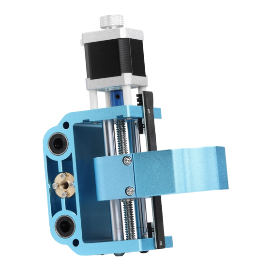
Aluminum xz axis assembly for cnc machine
Hide thumbs
Also See for 3018-PROVer Series:
- User manual (104 pages) ,
- User manual (85 pages) ,
- User manual

Related Manuals for Genmitsu 3018-PROVer Series


Summary of Contents for Genmitsu 3018-PROVer Series
- Page 1 Genmitsu Aluminum XZ Axis Assembly for 3018-PROVer Series CNC Machine Assembly Guide Aluminium XZ-Baugruppe für CNC-Maschinen der Serie 3018-PROVer Montageanleitung...
- Page 2 Dimension Suitable for 8mm trapezoidal screw Pitch: 2mm, Lead: 4mm...
-
Page 3: Package List
Package List Aluminum 43mm Spindle Z-axis Limit Assembly Z Axis Assembly Motor Mount Switch Cable Guide Preparation before assembly (please wear gloves before operation) Turn off the power supply. Disassemble the router bits, spindle motor and both sides of the Acrylic Baffle. - Page 4 STEP 1 Remove the Left Gantry Arm and Baffle ① Loosen and remove all screws, putting them aside for later use. ② Manually rotate the lead screw counterclockwise until the old XZ assembly can be fully removed. Left Baffle Original XZ Assembly X Axis Lead Screw...
- Page 5 STEP 2 Install the Upgraded XZ Assembly-Part 1 ① Align the X-axis screw with the T-nut hole of the Upgraded XZ Axis Assembly, insert it and rotate the screw clockwise by hand about 1.5 turns. ② Align the linear bearing hole of the Upgraded XZ Axis Assembly with the guide shaft and continue to rotate the screw until both guide shafts are all in the linear bearing hole.
- Page 6 STEP 3 Install the Upgraded XZ Assembly-Part 2 ① When the screw cannot be rotated clockwise by hand, reverse the screw 1-2 turns. ② Push the upgraded XZ Axis Assembly in the X + direction with your hand, while turning the screw clockwise with your right hand for 5-6 turns, observe that the screw is completely screwed into the left nut and then release your left hand and continue to rotate the screw so that the screw exceeds the left end of the upgraded head by about 20-30mm.
- Page 7 STEP 4 Install the Left Baffle ① Secure the left baffle with screws. ② Turn on the power to start the machine and use the control software to make the upgraded XZ Axis Assembly move between X+ and X– directions to check whether its movement is smooth.
- Page 8 STEP 5 Move the Gantry Backward ① Using the Allen wrench, turn the left and right side plate fixing screws 2 turns counterclockwise. ② At the same time, push the gantry assembly to move backward until the distance between the rear end face of the left and right vertical plates and the end face of the Y-axis motor fixing plate is 15mm.
- Page 9 STEP 6 Assembly Completed Turn off the machine and cut off the power, install the spindle motor, connect the spindle motor cable, Z-axis motor cable, Z+ Limit cable, and install the acrylic shield on both sides.
- Page 10 Change the Spindle Holder (Optional) There needs to be a separate section for mounting 52mm motors and the SainSmart lasers. Or it could be incorporated here. The machine is compatible with 52mm motors and by changing the spindle holder 65mm and 69mm trimmer routers such as Makita 65mm trimmer router and DEWALT 69mm trimmer router, by changing the spindle holder.
- Page 11 Abmessungen Suitable for 8mm trapezoidal screw Pitch: 2mm, Lead: 4mm...
- Page 12 Paketinhalt Aluminium XZ-Baugruppe Montageanleitung 43mm Spindel/Motor Hülse Z-Achsen Endschalter Kabel Montagevorbereitung (Bitte tragen Sie für die Montage Handschuhe) Trennen Sie die Maschine vom Stromnetz. Trennen und entfernen Sie die Kabel des Schrittmotors für die Z-Achse, das Anschlusskabel der Spindel sowie die beiden Kabel der Z-Achsen-Endschalter.
- Page 13 SCHRITT 1 Entfernen Sie das linke Seitenteil ① Lösen und entfernen Sie alle Schrauben des linken Seitenteils und legen Sie diese zur Seite. Sie werden später für die Montage wieder benötigt. ② Drehen Sie die Gewindespindel der X-Achse erneut mit der Hand gegen den Uhrzeigersinn, bis sich der Spindelhalter komplett von den Führungen und der Gewindespindel lösen lässt.
- Page 14 Montieren des XZ-Spindelhalter SCHRITT 2 Upgrade Teil 1 ① Führen Sie die Gewindespindel der X-Achse in die T-Mutter (Messing) ein, indem Sie die Gewindespindel mit der anderen Hand im Uhrzeigersinn drehen und die beiden Teile dadurch aufschrauben. ② Richten Sie die Gleitlager des XZ-Spindelhalters parallel zu den beiden Führungsstangen der X-Achse aus und drehen Sie die Gewindespindel weite, damit der XZ-Spindelhalter auf die Führungsstangen fährt.
- Page 15 Montieren des XZ-Spindelhalter SCHRITT 3 Upgrade Teil 2 ① Wenn die Gewindespindel nicht mehr weitergedreht werden kann, drehen Sie diese um 1-2 Umdrehungen zurück. ② Drehen Sie die Gewindespindel für 5-6 volle Umdrehungen im Uhrzeigersinn und üben Sie gleichzeitig von links kontinuierlich Druck auf den XZ-Spindelhalter aus.
- Page 16 SCHRITT 4 Montieren Sie das linke Seitenteil ① Befestigen Sie nun das linke Seitenteil. ② Tragen Sie nach Bedarf Schmiermittel sowohl auf die Gewindespindel als auch auf die Führungsstangen auf. ③ Verbinden Sie alle Anschlussleitungen (das Kabel für den Spindelmotor sollte dabei nicht mit der Steuerbaugruppe verbunden sein) und schalten Sie die Maschine ein.
- Page 17 SCHRITT 5 Ausrichten der Seitenteile ① Lösen Sie die unteren Schrauben am linken und rechten Seitenteil der Brücken Baugruppe, ohne diese jedoch zu entfernen. Verschieben Sie nun das gesamte Portal mit beiden Händen nach hinten, bis der Abstand zwischen der hinteren Kante des linken und rechten Portals und dem Ende der Motor Befestigungsplatte der Y-Achse 15 mm beträgt (wie in der Abbildung unten gezeigt).
- Page 18 SCHRITT 6 Montage abgeschlossen...
- Page 19 Wechseln des Spindelhalters Diese Maschine ist mit Oberfräsen kompatibel, indem der Spindelhalter ausgetauscht wird, z. B. mit 65mm Makita und 69mm DEWALT Oberfräsen. Sie müssen diese kompatiblen Spindelhalter separat bestellen. ① Zuerst lösen Sie die Schraube des originalen Motors und entfernen diesen mitsamt der Hülse.
- Page 20 Genmitsu If you need any assistance, please contact us via: Email: support@sainsmart.com Facebook messenger: https://m.me/SainSmart Help and support is also available from our Facebook Group Wenn Sie Hilfe benötigen, kontaktieren Sie uns bitte über: Email: support@sainsmart.com Facebook messenger: https://m.me/SainSmart Hilfe und Unterstützung finden Sie ebenfalls in unserer Facebook Gruppe...
Need help?
Do you have a question about the 3018-PROVer Series and is the answer not in the manual?
Questions and answers