Genmitsu 3018-PROVer Manual
Also See for 3018-PROVer:
- User manual (104 pages) ,
- Assembly manual (20 pages) ,
- User manual (85 pages)
Advertisement
Table of Contents
Genmitsu 3018-PROVer Manual
Preparation before assembly
(please wear gloves before operation)
- Turn off the power supply.
- Disconnect and remove the Z-axis stepper motor cable, spindle cable, Z+ limit switch cable and Z- limit switch cable.
- Disassemble the router bits, spindle motor and both sides of the Acrylic Baffle.
- Rotate the lead screw counterclockwise by hand or use the control software (move to the X-direction) to move the XZ assembly to the left side.


Assembly
STEP 1: Remove the left gantry arm and baffle
- Loosen and remove all screws, putting them aside for later use.
- Manually rotate the lead screw counterclockwise until the old XZ assembly can be fully removed.


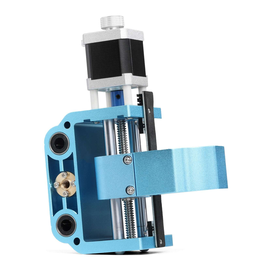
STEP 2: Install the Upgraded XZ Assembly-Part 1
- Align the X-axis lead screw with the copper nut hole and insert it while using your other hand to turn the lead screw clockwise, engaging the two parts.
- Align the XZ Assembly linear bearings hole with the linear rails on the X axis, and continue to rotate the lead screw to make both linear rails engage with the linear bearings.
- Manually rotate the screw clockwise to move the XZ assembly to the right until the screw cannot be turned by hand.


STEP 3: Install the Upgraded XZ assembly-Part 2
- When the screw cannot be rotated clockwise by hand, reverse the screw 1-2 turns.
- While applying continual pressure on the XZ assembly to the right, use your free hand to turn the lead screw clockwise for 5-6 full rotations. Once the leadscrew has engaged with the copper nut on the left side you can stop applying pressure and thread it through so that 20-30mm of the lead screw comes out the left of the XZ assembly.
- Examine your copper nut on the right of the XZ assembly. This should have a 0 5-2mm gap between the end side of the T-nut and the screw as shown below, so that the spring can work and eliminate the transmission gap.


STEP 4: Install the left baffle
- Reinstall the left gantry from step 1.
- Rub some lubricant on the X and Z axis lead screws as needed.
- Reinstall all wiring and turn on the power to run the machine; use the control software to move the XZ assembly between the X+ and X- directions to check whether its movement is smooth or not.
- If the lead screw got stuck when running, please adjust the tightness of the two linear rail screws as well as the position of the left baffle until the upgraded XZ assembly can move smoothly in the X axis direction.


STEP 5: Move the gantry backward
- Loosen the screws on the left and right gantry without removing them, and push the entire gantry assembly backwards with both hands until the distance between the rear end of the left and right gantry and the end of the Y-axis motor fixing plate is 15mm as shown in the illustration below.
- Turn off the power supply, install the spindle motor, connect the spindle motor cable, Z-axis stepper motor cable, Z+ Limit switch cable, Z- Limit switch cable, and re-install the acrylic baffle on both sides.


STEP 6: Assembly Completed

Dimension

Parameters
Z axis travel: 40mm
Stepper motor: NEMA17 48mm 1.7A stepper motor
Copper nut: Pitch: 2mm, Lead: 4mm
Limit switch: Normally open interface, terminal block XH2.54-3P
Application: Used for 3018PROVer upgrade ∮52mm spindle or DIY engraving machine.
Documents / ResourcesDownload manual
Here you can download full pdf version of manual, it may contain additional safety instructions, warranty information, FCC rules, etc.
Advertisement


Need help?
Do you have a question about the 3018-PROVer and is the answer not in the manual?
Questions and answers