Table of Contents
Advertisement
Available languages
Available languages
Quick Links
Advertisement
Chapters
Table of Contents

Related Manuals for Genmitsu 3040


Summary of Contents for Genmitsu 3040
- Page 1 Genmitsu Contents / Inhalt 3040 Aluminium Spoilboard for 3018 Y-axis Extension Kit English 01 - 09 3040 Aluminium-Arbeitsplatte für Y-Achsen Erweitungskit der 3018er Serie Deutsch 10 - 18 v1.0 Oct. 2021...
-
Page 2: Table Of Contents
Contents Package List Installation Step 1 Step 2 Step 3 Step 4 Step 5 Step 6 Step 7 Assembly Overview... -
Page 3: Package List
Package List Preparation before assemble: 1. Turn off the power supply.Disconnect and remove the Y-axis stepper motor cable and Y-axis limit switch cable. 2. Please wear gloves before operation. Allen Wrench, 4mm MDF Connecting Plate, Aluminum Profile, 300*180mm 300*360*9mm Allen Wrench, 5mm 11×Hexagon Socket 13×Hexagon Socket Screw 23×T-nuts, M6... -
Page 4: Installation
Installation Step 1: Disassemble the Acrylic Baffles and X aixs / Z axis Gantry... - Page 5 Installation Step 2: Y axis Base Disassembly ① Remove the Stock Side Profiles, Guide Rails and Lead Screw on both sides of the machine. ② Remove the Aluminum Profile, Sliders and Nut Seat, putting them aside for later use. Left Profile Right Profile Y axis Lead Screw...
-
Page 6: Step
Installation Step 3: Assemble the 3040 Upgraded Accessories ① Assemble two 3040 Guide Rails and 4 Sliders. ② Assemble 3040 Lead Screw and Nut Seat. ③ Assemble the Left and Right Side Profiles. 3040 Guide Rail Slider Left Profile Nut Seat... -
Page 7: Step
Installation Step 4: T-Nuts Positioning ① Place the original and new aluminum beds on a flat table as shown in the image below. ② Use the positioning tool to place the T-nuts to the desired position. M6 T-Nuts Positioning Tool Aluminum Profile... -
Page 8: Step
Installation Step 5: Connecting two Aluminum Profiles ① Place the MDF Board on Top of the Two Aluminum Beds so that the Holes Overlap with the T-Nuts from Step 4. ② Use M6*18 Hexagon Socket Screw with Flat Head to fix the Aluminum Beds and MDF Board. M6 *18 Hexagon Socket Screw with Flat Head... -
Page 9: Step
Step 6: Assemble the 3040 Platform ① Align the through holes on the Sliders and Nut Seat on the 3040 platform with the corresponding holes on the MDF Spoilboard and Plastic Spacer to make them concentric. Please note that Plastic Spacer should be placed between the Nut Seat, Sliders and the MDF Spoilboard. -
Page 10: Step
Installation Step 7: Assemble the original X aixs / Z axis Gantry ① Rotate the Lead Screw to check whether the Bed assembly moves smoothly along the Y Axis. If there is any abnormality, you need to adjust till it can move smoothly. ②... -
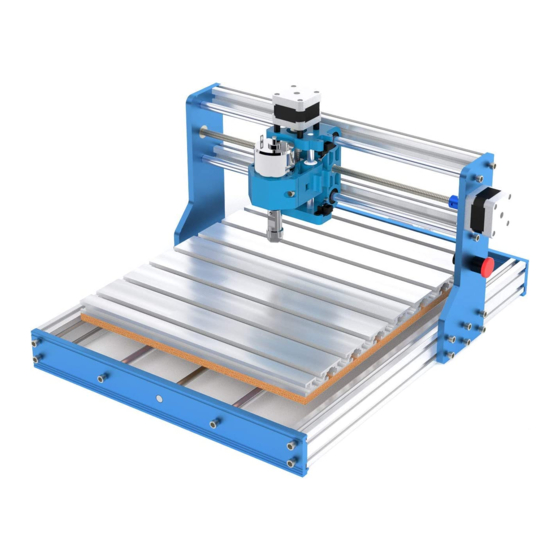
Page 11: Assembly Overview
Installation Assembly Overview... - Page 12 Inhaltsverzeichnis Lieferumfang Installation Schritt 1 Schritt 2 Schritt 3 Schritt 4 Schritt 5 Schritt 6 Schritt 7 Übersicht zur Montage...
-
Page 13: Lieferumfang
Lieferumfang Vorbereitung vor der Montage: 1.Schalten Sie die Stromzufuhr aus. Trennen und entfernen Sie das Kabel des Schrittmotors der Y-Achse und das Kabel des Endschalters der Y-Achse. 2.Bitte tragen Sie vor der Montage Handschuhe. Inbusschlüssel, 4mm MDF-Verbindungsplatte, Aluminum-Arbeitsplatte, 300*180mm 300*360*9mm Inbusschlüssel, 5mm 23×Nutenstein, M6 11×Schraube, M6*22mm... -
Page 14: Installation
Installation Schritt 1: Demontieren Sie die Acryl-Seitenwände und X-Achse / Z-Achse Brückenbaugruppe... - Page 15 Installation Schritt 2: Demontage der Y-Achsen Basisbaugruppe ① Entfernen Sie die Führungsschienen, die Leitspindel und die Rahmen auf beiden Seiten der Maschine. ② Entfernen Sie die ursprüngliche Aluminium-Arbeitsplatte und die blauen Gewindespindelhalterungen. Diese werden zur späteren Verwendung beiseite gelegt. Linker Rahmen Rechter Rahmen Y-Achsen Leitspindel...
-
Page 16: Schritt
Installation Schritt 3: Montieren Sie das Zubehör des 3040 Erweitungskits ① Montieren Sie zwei 3040 Führungsschienen und vier Gewindespindelhalterungen. ② Montieren Sie die 3040 Leitspindel und den Gewindespindelhalterung für Leitspindel. ③ Montieren Sie den linken und rechten Seitenrahmen. 3040 Führungsschiene... -
Page 17: Schritt
Installation Schritt 4: Positionierung der Nutensteinen ① Legen Sie die ursprüngliche und die neue Aluminium-Arbeitsplatte auf einen flachen Tisch, wie in der unteren Abbildung gezeigt. ② Verwenden Sie die Abstandhalter-Schablone, um die Nutensteinen in die richtige Position zu setzen. M6 Nutenstein Abstandhalter-Schablone Aluminum-Arbeitsplatte... -
Page 18: Schritt
Installation Schritt 5: Verbindung von zwei Aluminium-Arbeitsplatten ① Legen Sie die MDF-Platte auf die beiden Aluminium-Arbeitsplatte und achten Sie darauf, die Löcher der MDF-Platte mit den Nutensteinen aus Schritt 4 überlappen. ② Befestigen Sie die Aluminium-Arbeitsplatte und die MDF-Platte mit den M6*18 Schrauben. M6 *18 Schraube... -
Page 19: Schritt
Installation Schritt 6: Zusammenbau der 3040 Arbeitsplatte ① Richten Sie die Bohrungen an den Gewindespindelhalterungen auf der 3040 Arbeitsplatte mit den entsprechenden Löchern auf der MDF-Platte und dem Kunststoffabstandhalter aus. Bitte beachten Sie, dass der Kunststoffabstandhalter zwischen der Gewindespindelhalterung und der MDF-Platte platziert werden sollte. -
Page 20: Schritt
Installation Schritt 7: Montieren Sie die ursprüngliche X-Achse / Z-Achse Brückenbaugruppe ① Drehen Sie die Leitspindel, um zu prüfen, ob sich die Bettbaugruppe reibungslos entlang der Y-Achse bewegen kann. Wenn es nicht in Ordnung ist, müssen Sie es einstellen, bis es sich reibungslos bewegen kann. ②... -
Page 21: Übersicht Zur Montage
Installation Übersicht zur Montage... - Page 22 Copyright © 2021 by SainSmart All rights reserved. This manual or any portion thereof may not be reproduced or used in any manner whatsoever without the written permission of the publisher, except for the use of brief quotations embodied in critical reviews and certain other noncommercial uses permitted by copyright law. For permission requests, write to the publisher.
- Page 23 Genmitsu Desktop CNC & Laser www.sainsmart.com support@sainsmart.com Vastmind LLC, 5892 Losee Rd Ste. 132, N. Las Vegas, NV 89081...
Need help?
Do you have a question about the 3040 and is the answer not in the manual?
Questions and answers