
Subscribe to Our Youtube Channel
Related Manuals for Genmitsu CNC PROVerXL4030


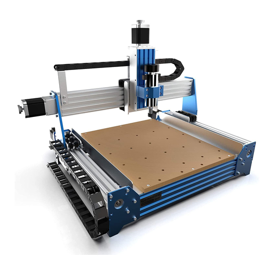
Summary of Contents for Genmitsu CNC PROVerXL4030
- Page 1 Genmitsu Contents / Inhalt 5.5W Laser Fixed Focus Module Kit for Genmitsu CNC PROVerXL4030 English 01 - 22 5,5W Laser-Module mit fester Brennweite für Genmitsu CNC PROVerXL4030 Deutsch 24 - 45 v1.1 Mar. 2022...
-
Page 2: Table Of Contents
Contents Welcome Safety Instructions 1 – What is in the box 2 – Description of the individual components 3 – Mounting the laser to a PROVerXL 4030 4 – Connecting to a PROVerXL 4030 5 – Installing LaserGRBL to use with PROVerXL 4030 6 –... -
Page 3: Welcome
Welcome Dear customer, Thank you for purchasing the Genmitsu 5.5W laser fixed focus module. This blue 5.5W diode laser with a wavelength of 445nm is especially designed for use with the Genmitsu CNC milling/engraving machines type PROVerXL 4030 & 3018-PRO. -
Page 4: Safety Instructions
Safety Instructions Always exercise safety and caution when working with laser marking systems. Consider the listed recommendations to minimize risk. · You must be at least 13 years old to operate the laser engraver. · Direct exposure to the laser beam can cause severe burns and eye damage. Ensure that you are wearing proper laser safety goggles when working in the vicinity of the laser equipment. -
Page 5: What Is In The Box
What is in the box Connecting Cable for Laser Head and Control Module Safety Goggles, adjustable (green) PROVerXL 4030, 3-Wire x 150cm Connecting Cable for 3018-PRO, 3 x T Nut, M3 x 10mm Laser Alignment Spacer x 20mm 3-Wire x 10cm 3 x Hexagon socket screw,... -
Page 6: Description Of The Individual Components
Description of the individual components Laser Head A 5.5W blue diode laser with a wavelength of 445nm. In order to ensure sufficient cooling, the laser is mounted in a heat sink, which is additionally equipped with a powerful yet quiet cooling fan. - Page 7 Description of the individual components Laser Control Module A Laser Control Module comes with the Laser Head itself, and acts as an intereface between it and your CNC, processing the PWM signal applied to the input. This results in the laser being supplied with the required voltage at the right time.
- Page 8 Description of the individual components On the other side of the Laser Control Module there are a number if connectors and a press switch. • External 12V DC 5A power source. • Fire / PWM Button, when in this is pressed 12V DC power in the laser is permanently on at 100% power, when out the laser power is...
-
Page 9: Mounting The Laser To A Proverxl 4030
Mounting the laser to a PROVerXL 4030 Preparation: Disconnect the spindle motor by removing the motor connection from the router Main board. Then remove the spindle motor from the motor mount. Also remove the four M5 screws from the motor mount. You will need these later to attach the bracket for the laser and the laser controller module. - Page 10 Mounting the laser to a PROVerXL 4030 STEP 1: Slide two additional M3 x 10mm T-nuts into the profile (above the existing M5 T-nuts). (2) M3 x 10mm T Nut...
- Page 11 Mounting the laser to a PROVerXL 4030 STEP 2: · Align the 3mm holes on the Laser Controller Module with the two 3mm holes on the profiles. · Fix the laser controller module to the profile with two M3 x 6mm Socket Cap Screws and adjust the position of the laser controller module.
- Page 12 Mounting the laser to a PROVerXL 4030 STEP 3: Fix the laser head to the bracket with four M3 x 8mm Socket Cap Screws. Laser Head Laser Head Bracket M3 x 8mm Socket Cap Screws...
- Page 13 Mounting the laser to a PROVerXL 4030 STEP 4: · Align the 5 mm holes of the holder for the laser head with the four 5 mm holes of the existing M5 T-nuts in the profiles. · Fix the laser controller module to the profile with four M5 x 10mm screws and adjust the position of the laser controller module.
- Page 14 Mounting the laser to a PROVerXL 4030 STEP 5: Installation Finished...
-
Page 15: Connecting To A Proverxl 4030
Connecting to a PROVerXL 4030 Connecting the Laser Control Module to a PROVerXL 4030 using the 3-pin cable for GND and PWM and +12v for the Laser Control Module. The 3-pin cable is connected to the middle socket of the router Main Board marked PWM. -
Page 16: Installing Lasergrbl To Use With Proverxl 4030
Installing LaserGRBL to use with PROVerXL 4030 LaserGRBL is a free program which works with Grbl based routers fitted with a Laser and Laser Engravers. It will be used here to assist with setting up the Laser, though it is capable of both sending GCode and converting images to G-Code for Laser Engraving It can be downloaded from https://lasergrbl.com/download/ After installation and connecting to the router the screen should look like this:... - Page 17 Installing LaserGRBL to use with PROVerXL 4030 There are a couple of customizations to be made before proceeding. Enable Z axis Jog Select ‘Grbl” → ‘Settings” and click on the ‘Jog Control” Tab. Make sure the ‘Click’n Jog” box is ticked and save.
- Page 18 Installing LaserGRBL to use with PROVerXL 4030 Add Custom buttons FIX URL Download the file CustomButtons.gz from our SainSmart WIKI at the following URL: http://wiki.sainsmart.com/index.php/SainSmart_Blue_Laser_Kit. Right click on the text ‘Right click here to add custom buttons’ in the Buttons pane and select ‘Import Custom buttons’. In the Open Window select the downloaded file and click Open.
- Page 19 Installing LaserGRBL to use with PROVerXL 4030 The LaserGRBL window should now look like this. The three added buttons are arranged from left to right and contain the following functions: Tun on laser at low power (S100), press again to turn off. Set for Laser mode ($32=1) Turn on the laser at low power (S100) for 2 seconds, then turn it...
-
Page 20: Use Lasergrbl To Set The Laser Height
Use LaserGRBL to set the laser height To cut or engrave efficiently we want the laser beam to be tightly focused into the smallest possible point at the top of the stock. Although the focus point of the Laser is fixed the height of the laser above the stock needs to be set correctly. -
Page 21: Use Lasergrbl To Focus The Laser Of Proverxl 4030
Use LaserGRBL to focus the laser of PROVerXL 4030 If desired test the focus of the laser by placing something which will not burn of a known thickness on top of stock underneath the laser. Now using the Z axis Jog controls jog up by the thickness of the item placed on the stock. -
Page 22: Use The Laser On A Grbl Based Router
Use the Laser on a Grbl based router When using a Laser in a Grbl based router such as the 3018-PRO there is an important mode setting in Grbl to tell it that it is using a Laser rather than a rotating spindle. This is $32 – Laser Mode. When using a Laser set the value to 1, when you remove the Laser and replace it with the spindle, motor set it back to 0 by sending a $32=0 command from your spindle control software. -
Page 23: Connecting To A 3018-Pro
Connecting to a 3018-PRO The first thing you should do is disconnect both sides of the electrical connection to the spindle motor. Then remove the spindle motor from the motor mount. Do not operate the SainSmart 3018-PRO with both the laser and the spindle motor connected! Slide the laser head into the motor mount so that the corners are in the slots of the motor mount and the cooling fan of the laser head pointing upwards. - Page 24 Connecting to a 3018-PRO The laser head has two 2-pin connection cables, one for the power supply of the cooling fan and one for the laser diode. Make sure that both cables are connected to the yellow and white pin socket of the laser control module as described above.
- Page 25 Inhalt Willkommen Warnhinweise 1 – Lieferumfang 2 – Beschreibung der einzelnen Komponenten 3 – Einbau des Lasers in eine PROVerXL 4030 4 – Anschluss an die PROVerXL 4030 5 – Installation von LaserGRBL für PROVerXL 4030 6 – Verwendung von LaserGRBL zum Einstellen der Laserhöhe 7 –...
-
Page 26: Willkommen
Willkommen Sehr geehrter Kunde, vielen Dank, dass Sie sich für das Genmitsu 5.5W Laser-Fixfokus-Modul entschieden haben. Dieser blaue 5,5 W Diodenlaser mit einer Wellenlänge von 445 nm ist speziell für den Einsatz mit den Genmitsu CNC-Fräs-/Graviermaschinen vom Typ PROVerXL 4030 & 3018-PRO konzipiert. -
Page 27: Warnhinweise
Warnhinweise Gehen Sie bei der Arbeit mit Lasermarkierungssystemen stets umsichtig und vorsichtig vor. Beachten Sie die aufgeführten Empfehlungen, um das Risiko von Schäden zu minimieren. · Sie müssen mindestens 13 Jahre alt sein, um den Lasergravierer zu bedienen. · Direkter Kontakt mit dem Laserstrahl kann zu schweren Verbrennungen und Augenschäden führen. Stellen Sie sicher, dass Sie eine geeignete Laserschutzbrille tragen, wenn Sie in der Nähe des Lasergeräts arbeiten. -
Page 28: Lieferumfang
Lieferumfang Anschlusskabel, Laserkopf und Schutzbrille, verstellbar (Grün) 3-adrig für PROVerXL 4030, Laser-Steuerbaugruppe l = 150 cm Anschlusskabel, Abstandshalter für Lasereinstellung, 3 x T-Nutenstein, 3-adrig für 3018-PRO, h = 20 mm M3 x 10 mm l = 10 cm 3 x Zylinderklopfschraube mit 4 x Senkkopfschraube mit Innensechskant, M3 x 6 mm Innensechskant, M3 x 8mm... -
Page 29: Beschreibung Der Einzelnen Komponenten
Beschreibung der einzelnen Komponenten Laser-Kopf Es handelt sich um einen 5,5W Laser mit blauer Diode und einer Wellenlänge von 445nm. Um eine ausreichende Kühlung zu gewährleisten, ist der Laser in einem Kühlkörper montiert; welcher zusätzlich mit einem leistungsstarken; aber dennoch laufruhigen Kühlgebläse ausgestattet ist. - Page 30 Beschreibung der einzelnen Komponenten Laser-Steuerbaugruppe Die zum Laserkopf passende Laser-Steuerbaugruppe ist im Lieferumfang des Laserkopfes enthalten und fungiert als Schnittstelle zwischen diesem und Ihrer CNC-Fräs-/Graviermaschine, indem sie das am Eingang anliegende PWM-Signal verarbeitet. Dies führt dazu, dass der Laser zum richtigen Zeitpunkt mit der erforderlichen Spannung versorgt wird.
- Page 31 Beschreibung der einzelnen Komponenten Auf der rechten Seite des Laser-Steuerungs-moduls befinden sich eine Reihe von Anschlüssen sowie ein Druckschalter. • Externe 12V DC 5A Spannungsversorgung • Feuer-/PWM-Schalter; wenn dieser 12V DC Spannungs- eingedrückt ist, so ist der Laser dauerhaft mit versorgung 100 % Leistung eingeschaltet, wenn er nicht eingedrückt ist, wird die Laserleistung...
-
Page 32: Einbau Des Lasers In Eine Proverxl 4030
Einbau des Lasers in eine PROVerXL 4030 Vorbereitungen: Trennen Sie zunächst die elektrische Verbindung des Spindelmotors beidseitig von der Steuer-Baugruppe der CNC Fräs-/Graviermaschine und entfernen Sie anschließend den Spindelmotor aus der Motorhalterung. Entfernen Sie hierzu auch die vier M5-Schrauben aus der Motorhalterung. Sie benötigen diese später zur Befestigung des Halters für den Laser sowie das Laser-Steuermodul. - Page 33 Einbau des Lasers in eine PROVerXL 4030 Schritt 1: Schieben Sie zwei zusätzliche M3 x 10mm T-Nutensteine in das Profil (oberhalb der vorhandenen M5 T-Nutensteine). (2) M3 x 10mm T-Nutensteine...
- Page 34 Einbau des Lasers in eine PROVerXL 4030 Schritt 2: · Richten Sie die 3 mm Bohrungen am Laser-Steuermodul mit den beiden 3mm Bohrungen der M3 x 10mm T-Nutensteine aus, · Befestigen Sie das Laser-Steuermodul mit zwei M3 x 6mm Zylinderklopfschrauben mit Innensechskant am Profil und justieren Sie die Position des Laser-Steuermoduls.
- Page 35 Einbau des Lasers in eine PROVerXL 4030 Schritt 3: Befestigen Sie den Laserkopf mit vier M3 x 8mm Senkkopfschrauben mit Innensechskant an der Halterung. Laserkopf Halterung für Laserkopf M3 x8mm Senkkopfschraube mit Innensechskant...
- Page 36 Einbau des Lasers in eine PROVerXL 4030 Schritt 4: · Richten Sie die 5mm Bohrungen der Halterung für den Laserkopf mit den vier 5mm Bohrungen der vorhandenen M5 T-Nutensteine in den Profilen aus. · Befestigen Sie das Laser-Steuermodul mit vier M5 x 10mm Schrauben am Profil und justieren Sie die Position des Laser-Steuermoduls.
- Page 37 Einbau des Lasers in eine PROVerXL 4030 Schritt 5 : Damit ist der Einbau des Lasers abgeschlossen.
-
Page 38: Anschluss An Die Proverxl 4030
Anschluss an die PROVerXL 4030 Anschluss des Laser-Steuermoduls an eine PROVerXL 4030 unter Verwendung des 3-poligen Kabels für den GND-, PWM- sowie +12V-Anschluss des Laser-Steuermoduls. Das 3-polige Kabel wird an die mittlere Buchse der Router-Steuerbaugruppe mit der Bezeichnung PWM angeschlossen. -
Page 39: Installation Von Lasergrbl Für Proverxl 4030
Installation von LaserGRBL für PROVerXL 4030 LaserGRBL ist ein kostenloses Programm, das mit GRBL-basierten CNC Fräs-/Graviermaschinen arbeitet, die mit einem Laser und Lasergravierern ausgestattet sind. Es wird hier verwendet, um bei der Einrichtung des Lasers zu helfen, obwohl es in der Lage ist, sowohl G-Code zu senden als auch Bilder für die Lasergravur in G-Code zu konvertieren. - Page 40 Installation von LaserGRBL für PROVerXL 4030 Bevor Sie fortfahren, müssen Sie einige Anpassungen vornehmen. Z-Aufwärts/Abwärts-Steuerung anzeigen Wählen Sie "Grbl" → "Einstellungen" und klicken Sie auf die Registerkarte "Jogging-Steuerung". Vergewissern Sie sich, dass das Kontrollkästchen "Z-Aufwärts/Abwärts-Steuerung anzeigen" aktiviert ist, und speichern Sie die Einstellung.
- Page 41 Installation von LaserGRBL für PROVerXL 4030 Benutzerdefinierte Schaltflächen hinzufügen Unter dem URL http://wiki.sainsmart.com/index.php/SainSmart_Blue_Laser_Kit. laden Sie sich zu-nächst aus unserem WIKI die Datei „CustomButtons.gz“ herunter. Klicken Sie anschließend mit der rechten Maustaste auf den Text „Right click here to add custom buttons“ in der Schaltflächenleiste von LaserGRBL und wählen Sie „Import custom buttons“.
- Page 42 Installation von LaserGRBL für PROVerXL 4030 Das LaserGRBL-Fenster sollte nun wie folgt aussehen. Dabei sind die drei hinzugefügten Schalt-flächen von links nach rechts angeordnet und beinhalten die folgenden Funktionen: Laser bei niedriger Leistung (S100) einschalten, zum Ausschalten erneut betätigen Lasermodus einschalten ($32=1) Laser bei niedriger Leistung (S100) für 2 Sekunden einschalten, danach wieder...
-
Page 43: Verwendung Von Lasergrbl Zum Einstellen Der Laserhöhe
Verwendung von LaserGRBL zum Einstellen der Laserhöhe Um effizient zu schneiden oder zu gravieren, muss der Laserstrahl so genau wie möglich auf einen möglichst kleinen Punkt fokussiert werden. Obwohl der Fokuspunkt des Lasers fixiert ist, muss der Abstand des Lasers über dem Material korrekt eingestellt werden. -
Page 44: Verwendung Von Lasergrbl Zur Laserfokussierung Beim Proverxl 4030
Verwendung von LaserGRBL zur Laserfokussierung beim PROVerXL 4030 Falls gewünscht, testen Sie die Fokussierung des Lasers, indem Sie etwas nicht brennbares Material mit einer bekannten Dicke auf die Fläche unter dem Laser legen. Verwenden Sie nun die Z-Achsen-Jog-Steuerung, um die Dicke des auf dem Material platzierten Gegenstands zu erhöhen. Klicken Sie auf die Schaltfläche „... -
Page 45: Verwendung Des Lasers Mit Einer Grbl-Basierten Cnc Fräs-/Graviermaschine
Verwendung des Lasers mit einer GRBL-basierten CNC Fräs-/Graviermaschine Bei der Verwendung eines Lasers in einer GRBL-basierten Fräs-/Graviermaschine wie der 3018-PRO gibt es in GRBL eine wichtige Moduseinstellung um festzulegen, dass ein Laser statt einer rotierenden Spindel verwendet wird. Dies ist „$32“, der Lasermodus. Wenn Sie einen Laser verwenden, setzen Sie den Wert auf „1“. -
Page 46: Einbau Des Lasers In Eine 3018-Pro
Einbau des Lasers in eine 3018-PRO Trennen Sie zunächst die elektrische Verbindung des Spindelmotors beidseitig von der Steuer-Baugruppe der CNC Fräs-/Graviermaschine und entfernen Sie anschließend den Spindelmotor aus der Motorhalterung. Betreiben Sie die SainSmart 3018-PRO nicht, wenn sowohl der Laser als auch der Spindelmotor gleichzeitig angeschlossen sind! Bewegen Sie die Motorhalterung mithilfe der Jog-Steuerung in die niedrigste Höhe. - Page 47 Einbau des Lasers in eine 3018-PRO Der Laserkopf verfügt über zwei jeweils 2-polige Anschlusskabel, eines für die Stromversorgung des Lüfters und eines für die Laserdiode. Stellen Sie sicher, dass beide Kabel wie zuvor beschrieben an die gelbe und weiße Stiftbuchse des Laser-Steuerungsmoduls angeschlossen sind. Das Laser-Steuerungsmodul kann an der Rückseite der CNC-Maschine mit den mitgelieferten M3 T-Muttern und Schrauben auf dem Aluminiumprofil rechts neben der Steuerung der CNC-Maschine montiert werden.
-
Page 48: Ce Und Safety Certificates Of Compliance
CE und Safety Certificates of Compliance... - Page 49 Genmitsu Desktop CNC & Laser www.sainsmart.com support@sainsmart.com Vastmind LLC, 5892 Losee Rd Ste. 132, N. Las Vegas, NV 89081...
Need help?
Do you have a question about the CNC PROVerXL4030 and is the answer not in the manual?
Questions and answers