
Related Manuals for Genmitsu 3020-PRO MAX V2


Summary of Contents for Genmitsu 3020-PRO MAX V2
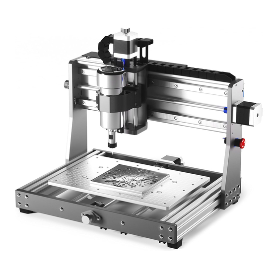
- Page 1 Genmitsu English 01 - 25 3020-PRO MAX V2 CNC Router Machine 3020-PRO MAX V2 CNC Fräs- und Graviergerät Deutsch 27 - 51 V1.0 May 2023...
-
Page 2: Table Of Contents
Contents Welcome Disclaimer Specifications Unboxing Optional Accessories (Not Included) Mechanical Installation Maintenance Wiring Software Setup Test Project Z Probe Setup... -
Page 3: Welcome
Welcome Thank you for purchasing the Genmitsu 3020-PRO MAX V2 CNC Router Machine from SainSmart. All your setup materials are on the included USB drive, located in your accessory box. Inside you will find: ● PDF version of this manual ●... -
Page 4: Disclaimer
Always place the CNC Machine on a stable surface. The 3020-PRO MAX V2 utilizes a high amp power supply. It is recommended that you do not plug the CNC Router into an extension cord, or power strip as it may damage the machine. -
Page 5: Specifications
Specifications Model Name 3020-PRO MAX V2 Work Area 300 x 205 x 78mm (11.81” x 8.07” x 3.07”) Overall Dimensions 484 x 394 x 388mm (19.04” x 15.49” x 15.28”) Control Board Compatibility GRBL 1.1h 32-Bit Max Speed 2000mm/min CAM Software Software Based on GRBL Firmware, e.g. -
Page 6: Unboxing
Unboxing XY Axis Base Assembly X-axis Assembly Spindle Motor Mount Spindle (4) Rubber Feet ER11 1/8” Collet Offline Controller USB A-to-B Cable Power Cord(US) - Page 7 Unboxing Power Cord (EU) X-axis Limit Switch Y-axis Limit Switch Offline Controller Cable (4) Clamp Kit Z-Probe Kit Wrench 20-degree V Bit (20) Cable Tie (13mm, 17mm)
- Page 8 Unboxing User Manual SD Card Card Reader Socket Head Cap Screw (17) M5×25 (5) M4 T-slot Nut (5) M4×10, (7) M4×16 Rounded Hex Screw 3mm Allen Wrench...
-
Page 9: Optional Accessories (Not Included)
Optional Accessories (Not Included) Consider following optional upgrades or accessories to make your CNC experience better! You can find them on www.sainsmart.com Compatible Compatible Compatible Y Axis Compatible MDF Spoilboard CNC Dust Shoe Extension Kit CNC Clamps... - Page 10 Dimension...
-
Page 11: Mechanical Installation
Mechanical Installation STEP 1 Installing Rubber Feet What you need: (4) M4×10 Socket XY Axis Base Assembly (4) Rubber Feet (4) M4 T-slot Nut Head Cap Screw Position the XY axis base assembly upside down on a flat surface as shown below, place the M4 T-slot nuts in the profile slot and install (4) rubber feet onto each corner with M4×10 socket head cap screws. - Page 12 Mechanical Installation STEP 2 Installing X-axis Assembly What you need: (16) M5×25 Rounded Hex Screw XY Axis Base Assembly X-axis Assembly Mount the X-axis assembly on the XY axis base assembly frame, ensure the X-Axis assembly is positioned all the way to the rear of the XY Base frame as shown below.
- Page 13 Mechanical Installation STEP 3 Spindle Motor Mount Installation What you need: (4) M4×16 Socket Spindle Motor Mount Head Cap Screw Install the spindle motor mount to Z - Axis Carriage using (4) M4×16 screws. (4) M4×16 Socket Head Cap Screw Spindle Motor Mount...
- Page 14 Mechanical Installation STEP 4 Installing Spindle Motor What you need: (4) M4×16 Socket Spindle Head Cap Screw Insert the spindle motor into the mount holder and secure it with (2) M4×16 screws. Spindle (2) M4*16 Socket Head Cap Screw...
-
Page 15: Maintenance
Maintenance Clean and lubricate the lead screw and exposed Y rods regularly to ensure normal operation of the machine. -
Page 16: Wiring
Wiring The new 3020-PRO MAX V2 is equipped with an all new Control board with auxiliary accessory ports allowing you to easily expand your machine and workflow. X-axis Motor Y-axis Motor Z-axis Motor Spindle Motor Handwheel Air Pump Laser Module... - Page 17 Wiring Connect the Y-axis limit switch cable to the Y-axis motor cable. Y-axis Motor Y-axis Limit...
- Page 18 Wiring Pull up the wire buckle and insert the spindle wiring. Red wire to red wire, black wire to black wire. Then press down the buckle, the spindle wiring is completed. Red Wire to Red Wire Black Wire to Black Wire...
- Page 19 Wiring WARNING: Please check your voltage selection on the power supply unit before powering on verify it is switched to the proper voltage for your region and connect your AC power cord. AC Input Voltage Adjustment Switch AC Power Cord Interface...
-
Page 20: Software Setup
Software Setup 1. Driver Installation Install the driver (software → Driver → CH340SER.exe) - Page 21 Software Setup 2. To Determine your Machines’ COM port: • Windows XP: Right click on "My Computer”, select "Manage", select "Device Manager". • Windows 7: Click "Start" → Right click "Computer” → Select "Manage" → Select "Device Manager" from the left pane. •...
- Page 22 Software Setup 3. Grblcontrol (Candle) Connecting to the Controller First time use will require you to set up the appropriate COM PORT and Baud rate. Step 1: Software should automatically select the port number. Step 2: If it does not recognize automatically select the "Baud” drop down menu and select 115200. Step 3: Click “OK”...
-
Page 23: Test Project
Test Project 1. Grblcontrol (Candle) - Page 24 Step 3: Click [ZeroXY] [Zero Z] Clear the XYZ axis coordinate. Step 4: Click [Send] running G-code. 3. About firmware parameters The parameters of the control board have been configured according to 3020-PRO MAX V2.
-
Page 25: Z Probe Setup
Z Probe Setup Probe function introduction 1. Grblcontrol (Candle) Probe operating instructions Step 1: Probe commands editing G90G21G38.2Z-50F100 Probe G code G92 Z14 G90 Z25 G21G91G38.2Z-20F100 Explanation: G0Z1 G21G91 : metric, relative coordinates G38.2Z-2F10 G21G91 : metric, relative moves After editing G92 Z12.35 G38.2Z-12.35F100 : probe 12.35 mm @ 100 mmpm G0Z1 : move up 1 mm (it's in relative, not absolute, mode... - Page 26 Z Probe Setup Step 2: Probe commands filled in Grblcontrol (Candle)
- Page 27 Z Probe Setup Step 3: Connect the probe tool to the controller probe interface. Step 4: Click the "Z-probe" button, Z-axis automatic tool to zero.
- Page 28 Inhalt Willkommen Haftungsausschluss Spezifikationen Lieferumfang Optionales Zubehör (nicht inkludie) Mechanischer Zusammenbau Wartung Anschluss Software-Einrichtung Test Projekt Messwerkzeug für Z-Achse...
-
Page 29: Willkommen
Willkommen Vielen Dank, dass Sie sich für das Genmitsu 3020-PRO MAX V2 CNC Router Kit von SainSmart entschieden haben. Alle zur Einrichtung benötigten Unterlagen befinden sich auf dem mitgelieferten USB-Stick, der sich in Ihrer Zubehörbox befindet. Dort finden Sie: ● PDF-Version dieses Handbuchs ●... -
Page 30: Haftungsausschluss
Stellen Sie sicher, dass die CNC-Maschine immer auf einem stabilen Untergrund steht. Die 3020-PRO MAX V2 arbeitet mit einem Hochstrom-Netzteil. Es wird empfohlen, die CNC-Fräsmaschine nicht an ein Verlängerungskabel oder eine Steckdosenleiste anzuschließen, da dies zu Schäden an der Maschine führen kann. -
Page 31: Spezifikationen
Spezifikationen Modellbezeichnung 3020-PRO MAX V2 Arbeitsbereich 300 x 205 x 78mm (11.81” x 8.07” x 3.07”) Gesamtabmessungen 484 x 394 x 388mm (19.04” x 15.49” x 15.28”) Steuerplatinen-Kompatibilität GRBL 1.1h 32-Bit Maximaler Vorschub 2000mm/min CAM Software Software basierend auf GRBL Firmware, z.B. Candle, UGS Material des Gehäuses... -
Page 32: Lieferumfang
Lieferumfang XY-Achsen Baugruppe X-Achsen Brücke Spindel Halterung Spindelmotor (4) Gummifüße ER11 1/8” Spannzange Offline-Controller USB A-to-B Kabel Netzkabel (US) - Page 33 Lieferumfang Netzkabel (EU) X-Achsen Endschalter Y-Achsen Endschalter Offline-Controller-Kabel (4) Klammer-Kit Z-Nullpunkt Sonde Maulschlüssel 20-Grad-V-Bit (20) Kabelbinder (13mm, 17mm)
- Page 34 Lieferumfang Benutzerhandbuch SD-Karte Kartenleser Zylinderschraube mit (17) M5×25 Innensechskant (5) M4 T-Nut-Mutter Linsenkopf-Schraube (5) M4×10, (7) M4×16 3mm Innensechskantschlüssel...
-
Page 35: Optionales Zubehör (Nicht Inkludie)
Optionales Zubehör (nicht inkludie) Ziehen Sie die folgenden optionalen Upgrades oder Zubehörteile in Betracht, um Ihre CNC-Erfahrung zu verbessern! Sie finden sie auf www.sainsmart.com Kompatible Kompatibler Kompatibles Verlängerungsset Kompatible MDF-Abfallplatte CNC-Staubschutzschuh für die Y-Achse CNC-Klemmen... - Page 36 Abmessungen...
-
Page 37: Mechanischer Zusammenbau
Mechanischer Zusammenbau SCHRITT 1 Anbringen der Gummifüße Was wird benötigt: (4) M4×10 Zylinderschraube XY-Achsen Baugruppe (4) Gummifüße (4) M4 T-Nut-Mutter mit Innensechskant Legen Sie die XY-Achsen Baugruppe, wie unten gezeigt, umgedreht auf eine ebene Fläche. Setzen Sie nun (4) M4-Nutensteine in den Profil-Schlitz und montieren Sie (4) Gummifüße an jeder Ecke mit den M4×10-Innensechskantschrauben. - Page 38 Mechanischer Zusammenbau SCHRITT 2 Installation der X-Achsen Baugruppe Was wird benötigt: (16) M5×25 Linsenkopf-Schraube XY-Achsen Baugruppe X-Achsen Brücke Montieren Sie die X-Achsen Brücke auf der XY-Achsen Baugruppe. Stellen Sie sicher, dass diese, wie unten gezeigt, ganz hinten am XY-Basisrahmen positioniert ist. Schließen Sie die Installation ab, indem Sie die X-Achsen Brücke mit (8) M5×25 Schrauben je Seite am Rahmen befestigen.
- Page 39 Mechanischer Zusammenbau SCHRITT 3 Montage der Spindel Halterung Was wird benötigt: (4) M4×16 Zylinderschraube Spindel Halterung mit Innensechskant Montieren Sie die Spindel Halterung mit (4) M4×16 Schrauben am Z-Achsen Schlitten. (4) M4×16 Zylinderschraube mit Innensechskant Spindel Halterung...
- Page 40 Mechanischer Zusammenbau SCHRITT 4 Einbau des Spindelmotors Was wird benötigt: (4) M4×16 Zylinderschraube Spindelmotor mit Innensechskant Insert the spindle motor into the mount holder and secure it with (2) M4×16 screws. Spindelmotor (2) M4×16 Zylinderschraube mit Innensechskant...
-
Page 41: Wartung
Wartung Reinigen und schmieren Sie die Leitspindeln sowie Führungsschienen regelmäßig, um einen normalen Betrieb der Maschine zu gewährleisten. -
Page 42: Anschluss
Anschluss Die neue 3020-PRO MAX V2 ist mit einer komplett neu designten Steuerplatine ausgestattet, welche mit seinen zusätzlichen AUX Anschlüssen erweitert sowie auf Ihren Workflow angepasst werden kann. X-Achsen Motor Y-Achsen Motor Z-Achsen Motor Spindelmotor Handrad Compressor Laser Modul USB Kabel... - Page 43 Anschluss Verbinden Sie das Kabel des Y-Achsen Endschalters und des Y-Achsen Schrittmotors mit der Platine, siehe nachfolgende Abbildung: Y-Achsen Motor Y-Achsen Endschalter...
- Page 44 Anschluss Um den Spindelmotor anzuklemmen, öffnen Sie die orangenen Bügel des Verbinders und führen Sie die Kabel entsprechend ein. Rotes Kabel zu rot und schwarz zu schwarz. Im Anschluss schließen Sie die Bügel und der Anschluss des Spindelmotors ist erledigt. Rotes Kabel an rotes Kabel Schwarzes Kabel auf schwarzes Kabel...
- Page 45 Anschluss WARNUNG: Bitte prüfen Sie vor dem ersten Einschalten, dass am Netzteil die korrekte Versorgungsspannung, entsprechend Ihrer Hausversorgung eingestellt ist. Erst jetzt schließen Sie das Netzkabel an. AC-Eingangsspannungs-Einstellschalter AC-Netzkabel-Schnittstelle...
-
Page 46: Software-Einrichtung
Software-Einrichtung 1. Installation des Treibers Installieren Sie zunächst den Treiber (Software → Treiber → CH340SER.exe). - Page 47 Software-Einrichtung 2. So bestimmen Sie den COM-Anschluss Ihres Geräts: • Windows XP: Klicken Sie mit der rechten Maustaste auf "Arbeitsplatz", wählen Sie "Verwalten", wählen Sie "Geräte-Manager". • Windows 7: Klicken Sie auf "Start" → Rechtsklick auf "Computer" → Wählen Sie "Verwalten" → Wählen Sie "Geräte-Manager" aus dem linken Fenster.
- Page 48 Software-Einrichtung 3. Grblcontrol (candle) starten Bei der erstmaligen Verwendung müssen Sie den entsprechenden COM PORT und die Baudrate einrichten. Schritt 1: Die Software sollte automatisch die Portnummer auswählen. Schritt 2: Sollte dies nicht der Fall sein, wählen Sie das Dropdown-Menü "Baud" und wählen Sie 115200. Schritt 3: Klicken Sie auf "OK", um zu speichern.
-
Page 49: Test Projekt
Test Projekt 1. Grblcontrol (Candle) 3D-Vorschau: halten Sie die linke Maustaste, um den Koordinatenanzeige Winkel zu verändern. Scrollen Sie das Mausrad zum Vergrößern oder Schaltflächen für Verkleinern. manuelles Verfahren. Das Maussymbol oben zeigt die Wenn Sie nichts sehen spezifische Funktion können, müssen Sie auf einen Computer mit Anklicken zum Erweitern... - Page 50 Werkzeug und das Werkstück sich gerade berühren. Schritt 3: Klicken Sie auf [ZeroXY] [Zero Z] Löschen Sie die XYZ-Achsenkoordinate. Schritt 4: Klicken Sie auf [Senden], um den G-Code auszuführen. 3. Über Firmware-Parameter Die Parameter der Steuerplatine wurden entsprechend der 3020-PRO MAX V2 konfiguriert.
-
Page 51: Messwerkzeug Für Z-Achse
Messwerkzeug für Z-Achse Gebrauch des Messwerkzeugs 1. Nutzung von Grblcontrol (Candle) mit dem Messwerkzeug Schritt 1: Bearbeitung der Befehle G90G21G38.2Z-50F100 Erläuterung: G-Code für Messwerkzeug G92 Z14 G21G91 : metrisch, relative Koordinaten G90 Z25 G21G91 : metrische, relative Bewegungen G21G91G38.2Z-20F100 G38.2Z-12.35F100 : Sondenmessung 12.35 mm @ 100 mmpm G0Z1 G0Z1 : Bewegung um 1 mm nach oben (relativer Modus, nicht G38.2Z-2F10... - Page 52 Messwerkzeug für Z-Achse Schritt 2: Sondenbefehle in Grblcontrol ausgefüllt. Fügen Sie hier die Befehle ein...
- Page 53 Messwerkzeug für Z-Achse Schritt 3: Schließen Sie das Sondenwerkzeug an die dafür vorgesehene Schnittstelle des Controllers an. Gelber Stecker „Z Probe Kit“. Schritt 4: Klicken Sie auf die Schaltfläche "Z-Probe", Z-Achse automatische Werkzeug auf Null. Drücken Sie auf das „Z-probe“ Bedienelement...
- Page 54 Genmitsu Desktop CNC & Laser Email: support@sainsmart.com Facebook messenger: https://m.me/SainSmart Help and support is also available from our Facebook Group Vastmind LLC, 5892 Losee Rd Ste. 132, N. Las Vegas, NV 89081 Facebook Group...
Need help?
Do you have a question about the 3020-PRO MAX V2 and is the answer not in the manual?
Questions and answers
What type of lubricant do you recommend to use for the linear rods, rails and screws?