Table of Contents
Advertisement
Quick Links
Advertisement
Table of Contents

Related Manuals for Rayleigh Instruments RI-ENERGYFLOW-MODULAR Series


Summary of Contents for Rayleigh Instruments RI-ENERGYFLOW-MODULAR Series
- Page 1 Telephone : +44 (0) 1245 428500 Email : sales@rayleigh.com RI-ENERGYFLOW-MODULAR Series Modular Inverters 3.68kW | 5.0kW User Manual Rayleigh Instruments Limited www.rayleigh.com Raytel House, Cutlers Road, South Woodham Ferrers, Chelmsford, Essex CM3 5WA UK...
-
Page 2: Table Of Contents
Table of Contents Document Introduction ............................ 4 1.1 Introduction ..........................4 1.2 Applied Symbols ..............................4 1.3 Important afety Information ..................... 5 1.4 System Sizing........................... 7 2. System Overview ..........................8 ........ 2.1 System onfiguration ....................... 8 2.2 Operation Modes ........................ - Page 3 Telephone : +44 (0) 1245 428500 Email : sales@rayleigh.com 7. Alarm ode and rror ode s ......................43 7.1 Alarm Code ..........................43 7.2 Error Code ..........................43 8. Fault iagnosis and olutions ....................44 9. Machine Parameters ......................... 45 9.1 Technical Data –...
-
Page 4: Document Introduction
Document Introduction Introduction This manual describes solar inverters: RI-ENERGYFLOW-MODULAR-3.68kW /5.0kW. These inverters are Battery Isolation based inverter. Please read the safety instructions in this manual first. Throughout the manual it is assumed that the reader is familiar with AC and DC installations and knows the rules and regulations for electrical equipment and for connecting it to the utility AC grid. -
Page 5: Important Afety S Information
Telephone : +44 (0) 1245 428500 Email : sales@rayleigh.com Important safety information Read this before installing, operating or maintaining the inverter. Before installation: Check for damage to inverter and packaging. If you are in doubt, please contact your supplier before installing the inverter. Check the voltages of the solar modules and make sure they are within the limits of the inverter specifications before connecting them to the inverter. - Page 6 1.3.4 Operation After Power Failure The battery system is part of the energy storage system which stores life-threatening high voltage even when the DC side is switched off. Touching the battery outlets is strictly prohibited. The inverter can store ethal voltage levels even after disconnect...
-
Page 7: System Sizing
Telephone : +44 (0) 1245 428500 Email : sales@rayleigh.com • Do not put any heavy objects on top of the system. • Do not damage the system with sharp objects. • Do not install or operate the system in potentially explosive atmospheres or areas of high humidity. •... -
Page 8: System Overview
System Overview System configuration RI-ENERGYFLOW-MODULAR inverters can be applied in DC-coupled systems ( usually new installation), AC coupled systems ( usually retrofit) and Hybrid -coupled systems ( usually retrofit to increase PV capacity ), as the following schemes show: Configuration Solution ve te Module Battery Module(s) -
Page 9: Operation Modes
Telephone : +44 (0) 1245 428500 Email : sales@rayleigh.com Figure 2 AC-coupled Storage System–Scheme Figure and DC (Hybrid) coupled Storage System –Scheme Operation Modes There are three basic modes that end users can choose via inverter screen/APP. • SELF CONSUME: The energy generated by the solar panels will be used in the following order: Feed the home loads;... - Page 10 • BAT PRIORITY: The battery is only used as a backup power supply when the grid fails. As long as the grid works, the batteries won’t be used to power the loads. The battery is charged with the power generated by the PV system or from the grid.
-
Page 11: Dimensions
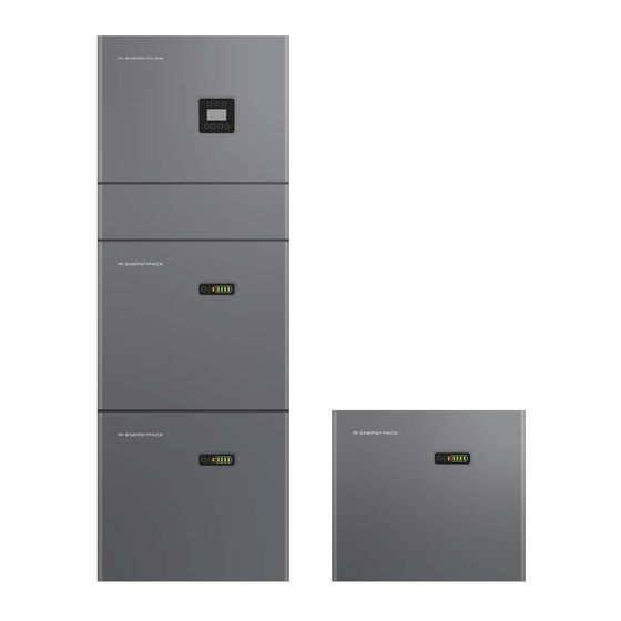
Telephone : +44 (0) 1245 428500 Email : sales@rayleigh.com 2.3 Dimensions Inverter and 1 x Battery Module Inverter and 2 x Battery Modules 1 x Battery Module 2 x Battery Modules Module Depth: 240mm Mounted Module Depth: 270mm (Including Mounting Bracket) Page 11... -
Page 12: Getting Started: Included Accessories And Wiring Kits
2.4 Getting Started: Included Accessories and Wiring Kits Included Accessories Inverter Module Accessories: 4off M5x12mm Screws 2 pairs of MC4 plugs 1off WIFI Module 1off AC Grid Connector 1off Back-up Connector and 2.5mm Allen Key 2off Mounting Screws 1off CT/ Meter Connector 1off... - Page 13 Telephone : +44 (0) 1245 428500 Email : sales@rayleigh.com Wiring Kits One battery installation using wiring kit RI-MOD-KIT5.1 Communication Cables: 300mm Power Cables (Black): 250mm Power Cables (Red): 250mm PE Cables: 700mm Two battery installation using wiring kit RI-MOD-KIT10.2 Communication Cables: 300mm 570mm Power Cables (Black):...
- Page 14 Three battery installation using wiring kit RI-MOD-KIT15.3 Communication Cables: 300mm 570mm 1700mm Power Cables (Black): 250mm 485mm 1800mm Power Cables (Red): 485mm 1900mm 2800mm PE Cables: 520mm 700mm 1700mm Four battery installation using wiring kit RI-MOD-KIT20.4 Communication Cables: 300mm 570mm 1700mm Power Cables (Black): 250mm...
-
Page 15: System Appearance And Connections
Telephone : +44 (0) 1245 428500 Email : sales@rayleigh.com 2.5 System Appearance and Connections Figure 7 RI-ENERGYFLOW-MODULAR components Object Description RI-ENERGYFLOW-MODULAR Inverter (3.68kW or 5kW) Inverter Display Screen Cable Box (connected to inverter) RI-ENERGYPACK-MODULAR Battery 1 RI-ENERGYPACK-MODULAR Battery 2 (if configured) Table 2 RI-ENERGYFLOW-MODULAR components 2.5.1 Cable Box Part Figure 8 Inverter without Cable Box Covers–... - Page 16 External Connections Using the connectors described in the Getting Started section within this guide, proceed to connect the applicable items described in the below table. Connect the included WIFI module to the connector. All wiring must be performed in accordance with local wiring regulations. Table 3 RI-ENERGYFLOW-MODULAR Cable Box Object Designation...
- Page 17 Telephone : +44 (0) 1245 428500 Email : sales@rayleigh.com Figure 9 Cable Box Part without Covers – Front View Object Description Battery circuit breaker DC isolation switch Output terminal block (BACK UP/ON GRID) Page 17...
-
Page 18: Liability Limitation
2.6 Liability Limitation Any product damage or property loss caused by the following conditions, Rayleigh Instruments does not assume any direct or indirect liability. • Product modified, the design changed or parts replaced without Rayleigh Instruments authorization; unqualified personnel; •... - Page 19 Telephone : +44 (0) 1245 428500 Email : sales@rayleigh.com 3.1.2 Restricted Locations RI-ENERGYFLOW-MODULAR shall not be installed : (a) In restricted locations as defined for panels in AS / NZS 3000. (b) within 600mm of any heat source, such as hot water unit, gas heater, air conditioning unit or any other appliance.
-
Page 20: Installation Procedures
3.2 Installation Procedures Figure 11 Limited Distance of Installation to Neighboring Objects Battery Installation - Note: The installation location must be in accordance with the previous chapter Step 1: Attach the supplied wall mounting bracket to the battery module using the supplied M5x12mm screws. M5*12 Screws Step 2: Place the battery module against the wall and mark the 4 holes indicated below that are to be drilled. - Page 21 Telephone : +44 (0) 1245 428500 Email : sales@rayleigh.com Step 3: Remove any debris. Secure the battery module to the wall using the supplied mounting screws and M6 washers. On the last battery module of the stack, leave the two central screws unfitted and proceed to the next section for Inverter Installation M6 Washers Step 4: Repeat steps 1-3 for any additional batteries.
- Page 22 Step 2: Remove any debris. Secure the inverter bracket to the wall using the supplied screws (2 from battery installation + washers for the bottom holes and 2 without washers for the top holes). Step 3: Fit the inverter on to the bracket. Take care to ensure the rear tang correctly engages with the bracket. Step 4: Loosely fit the 4xM5x12mm screws through the battery brackets in to the inverter.
- Page 23 Telephone : +44 (0) 1245 428500 Email : sales@rayleigh.com 3.2.1 Wiring and connections . Please make AC cables on site. Wiring sizing to be in accordance with local wiring regulations There are"L" "N'' '' '' symbols marked inside the connector, the Line wire of grid must be connected to "L"...
- Page 24 e. Screw the swivel nut onto the threaded sleeve. This seals the AC connector and provides strain relief for the AC cable. When doing so, hold the bush insert firmly by the locking cap. This ensures that the swivel nut can be screwed firmly onto the threaded sleeve.
- Page 25 Telephone : +44 (0) 1245 428500 Email : sales@rayleigh.com 3. Connect the AC wiring terminal to the corresponding hole site of the inverter and lock it with a screwdriver or electric screwdriver (suggestion: stem diameters and torsion of a screwdriver or electric screwdriver should be 4mm and 8~12kg-f.cm respectively) and tighten the nut.
- Page 26 7. Connect the power cables of the bottom battery from S tep 4 to the side terminals of the top battery. Make sure that red connects to red and black connects to black. 8. Close the battery covers and connect the PV -MC4 connectors to the system (connection on both sides). Also, connect all AC cables, the meter communications cable METER, and the Ethernet cable LAN.
- Page 27 Telephone : +44 (0) 1245 428500 Email : sales@rayleigh.com If you connect more than 2 battery modules to the system, only install the additional batteries 5-6 (third module) on the side of the system. You can connect up to 6 batteries (three modules), each 2 batteries are mounted on top of each other.
- Page 28 3.3 External CT or Meter with CT Connection In order for the system to work correctly, a load sensing current transformer MUST be installed. Alternatively, an external Modbus meter may be used. Meter installation and current transformer installation is described below.
-
Page 29: Dred Port Connection (Optional)
Telephone : +44 (0) 1245 428500 Email : sales@rayleigh.com 3.4 DRED Port Connections (Optional) DRED means demand response enable device. The AS/NZS 4777.2:2015 required inverter need to support demand response mode (DRM). This function is for the inverter that complies with AS/NZS 4777.2:2015 standard. -
Page 30: System Operation
Figure 15 AC-coupled system Figure 16 Hybrid-coupled system 4. System Operation 4.1 Switch On When turning on the system, it is necessary to follow the steps below to prevent damage to the system. Please check the installation again before turning on the system •... -
Page 31: Switch Off
Telephone : +44 (0) 1245 428500 Email : sales@rayleigh.com the Backup switch is only used when a backup load is applied. • Open the outer shell of the cable box. Open the battery switch cover and turn on the battery switch on the cable-box. - Page 32 Check the control power supply. If it is OK, return the power supply to find out the rea son. • Please record every detail related to the fault, so Rayleigh Instruments can analyse and solve the fault. Any operation of equipment during a fault is strictly forbidden, please contact Rayleigh Instruments as soon as possible.
-
Page 33: Inverter And Battery Module Displays
Telephone : +44 (0) 1245 428500 Email : sales@rayleigh.com 5. Inverter and Battery Module Displays 5.1 Function Description Figure 18 RI-ENERGYFLOW-MODULAR-EMS Interface (Left) / RI-ENERGYPACK-MODULAR interface (Right) Object Name Description Green: Grid connection (Solid). Not connected (Flashing) Indicator LED Green: Indication of Off-grid status Red: The inverter is in fault. -
Page 34: Online Display
5. 2 Online Display Pages The inverter online pages will are shown below. The displayed page will change every 3 seconds automatically. If the user wishes to manually cycle through the pages, use the UP and DOWN buttons. If the user wishes to stop the pages cycling, press the ENTER key to lock the current screen. - Page 35 Telephone : +44 (0) 1245 428500 Email : sales@rayleigh.com BMS PARAM CHAR VOLT : Battery Charging Voltage CHARGE : Battery Charging Current DISCHARGE : Battery Discharging Current GRID DATA Mains Voltage VOLT : 239.8V Mains Current CURR : 0.00A Mains Frequency FREQ : 50.12Hz INV DATA...
- Page 36 TEMPERATURE Inverter Heat-sink Temperature INV : 23.1°C DC-DC Heat-sink Temperature DCDC : 21.5°C Internal Ambient Temperature AMBIENT : 24°C STATE Current System Status SYS : G-BYPASS INV : STANDBY Current Inverter Status DCDC : STANDBY Current DC-DC Status ERROR NO. WARNING : W20-1 Warning Code...
-
Page 37: Programming Menu
Telephone : +44 (0) 1245 428500 Email : sales@rayleigh.com 5.3 Programming Menu Menu Path: Setup > Enter Password (Default 00000) > SYS Setting: The energy generated by the solar panels will be used in Charge the following order: Feed the home loads; Charge the from battery and then, feed into the grid. - Page 38 Menu Path: Setup > Enter Password (Default 00000) > SYS Setting: (CONTINUED) Menu Path: Setup > Enter Password (Default 00000) > SYS Setting: (CONTINUED) Disable Depth of discharge. This should always be enabled. DOD Enable Enable Enable Disabling will result in the battery discharging to 0% Disable This option allows the user to install a secondary means Generator...
- Page 39 Telephone : +44 (0) 1245 428500 Email : sales@rayleigh.com Menu Path: Setup > Enter Password (Default 00000) > Grid STD): 1. China 13. Thailand 2. Germany 14. South Africa 3. Australia 15. 50549 4. Italy 16. Brazil 5. Spain 17. 0126 6.
- Page 40 Menu Path: Setup > Enter Password (Default 00000) > All other settings within Setup Allows the user to select the RS485 address for the COM 1…255 Address port 1. 2400 Allows the user to select the RS485 serial baud rate for Baud Rate 2.
- Page 41 Telephone : +44 (0) 1245 428500 Email : sales@rayleigh.com 6 Battery storage and recharging 6.1 Battery storage requirements 1. Storage environment requirements: –ambient temperature: -10℃...45℃; recommended storage temperature: 20℃...30℃; –relative humidity: 0% 90%RH; –in a dry, ventilated and clean place; –no contact with corrosive organic solvents, gases and other substances;...
- Page 42 6.4 Recharge Operation Steps Step 1 Connect power cables to the battery charger correctly. The maximum number of battery PACK connected parallel is 5. Step 2 Turn on the battery PACK DC breaker to ON; Press the battery “ start key” for 3 second to start the battery PACK.
-
Page 43: Alarm Ode And Rror Ode C S E C S
Telephone : +44 (0) 1245 428500 Email : sales@rayleigh.com 7. Alarm code and error code 7.1 Alarm Code Codes Description Grid Volt Low Grid Volt High Grid Frequency Low Grid Frequency High Solar Loss Bat Loss Bat Under Volt Bat Volt Low Bat Volt High Over Load GFCI Over... -
Page 44: Fault Iagnosis And Olutions D S
Sink Over Temp Grid Relay Fault DisChg Curr Over Chg Curr Over Current Sensor Fault INV Abnormal EPS Relay Fault Alway Over Load SCI Fault 8. Fault diagnosis and solutions Types Codes Solutions (1) Restart the inverter and wait until it functions normally;... -
Page 45: Machine Parameters
Telephone : +44 (0) 1245 428500 Email : sales@rayleigh.com (2) Check whether the load is in compliance with the specification; (1) Check PV string for direct or indirect grounding phenomenon; CFCI Over (2) Check peripherals of machine for current leakage; (3) Contact the local inverter customer service if fault remains unremoved. - Page 46 Max. Output Current Harmonic distortion [THD] at rated output <2% (Linear Load) Automatic Switch Time <20ms Peak power [VA], Duration 6900VA, 10s Battery Input Data Battery Type LFP (LiFePO4) Nominal Battery Voltage 51.2V Max. Charging Voltage 57.6V Max. Charging/Discharging Current 50A / 80A 100A / 100A Communication interfaces...
- Page 47 Telephone : +44 (0) 1245 428500 Email : sales@rayleigh.com (2) Check whether the load is in compliance with the specification; (3) Contact customer service if error warning continues. (1) Restart the inverter and wait until it functions normally. INV DC Over (2) Contact customer service if error warning continues.
-
Page 48: Technical Data - Batteries
9.2 Technical Data – Batteries Model – RI-ENERGYPACK-MODULAR 5.1kWh 10.2kWh 15.3kWh Nominal Energy 5.12kWh 10.24kWh 15.36kWh Voltage Range 44.8V…56.5V Nominal Voltage 51.2V Max. Charging Current 100A 100A Max. Discharging Current 100A 100A Battery Type LFP (LiFePO4) Communication CAN and RS485 compatible Max. -
Page 49: 3 . Grid Specifications
Telephone : +44 (0) 1245 428500 Email : sales@rayleigh.com 9 3 . Grid Specifications Grid Output Voltage Range Output Frequency Range Boot wait time(S) Specification (Vac) (Hz) China 187-252 48-50.5 Germany 184-264 47.5-51.5 Australia 180-260 47-52 Italy 184-276 49.7-50.3 Spain 196-253 48-50.5 U.K. -
Page 50: Routine Maintenance
1 . Routine Maintenance 1 .1 Maintenance Plan • Check if wire connections are loose. • Check if cables are aged/damaged. • Check if cable insulating ribbon drops. • Check if the cable terminal is loose, any overheat sign. • Check if the ground connection is good. -
Page 51: Quality Assurance
Conditions • After replacement, unqualified products shall be processed by Rayleigh Instruments. • The customer shall give Rayleigh Instruments or his partner a reasonable period to repair the faulty device. Exclusion of Liability In the following circumstances, Rayleigh Instruments has the right to refuse to honour the quality guarantee: •... - Page 52 Eastern European Offi Offi ce : ce : Rayleigh Instruments Sp. z o.o. Rayleigh Instruments Sp. z o.o. ul. Aleje Jerozolimskie 214, 02-486, Warszawa. Poland. ul. Aleje Jerozolimskie 214, 02-486, Warszawa. Poland. Telephone : +48 22 290 27 26 Telephone : +48 22 290 27 26 www.rayleigh.pl...
Need help?
Do you have a question about the RI-ENERGYFLOW-MODULAR Series and is the answer not in the manual?
Questions and answers