Advertisement
Quick Links
Quick Start Installation Guide
Getting Started
Step 1: Remove all modules from the cardboard boxes and associated packaging materials. Ensure that the brackets and included
accessories are kept.
Step 2: Inspect all parts for damage. Do not proceed with the installation if damage is observed. If in doubt please call the supplier.
Step 3: Ensure all accessories are present and correct. The included accessories should be as shown below.
Inverter Module Accessories:
4off M5x12mm Screws
2off Mounting Screws
and Nylon Wall Plugs
Battery Module Accessories:
4off Mounting Screws
and Nylon Wall Plugs
**An additional wiring kit will be required if the installation contains more than one battery module. Refer to table below.
Wiring Kits for Additional Battery Modules:
Total Number Of Battery Modules
Rayleigh Instruments Limited
2 pairs of MC4 plugs
1off CT/ Meter Connector
(4Way)
3off M5x12mm Screws
2
3
4
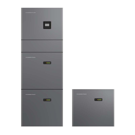
RI-ENERGYFLOW-MODULAR SERIES
Installation safety precautions:
This system must only be installed by qualified personnel
Ÿ
familiar with applicable wiring regulations.
Isolate all power supplied to the device prior to undertaking
Ÿ
any work on the system.
Check all wiring connections before energising any part of
Ÿ
the system.
Do not remove or dismantle the device modules. There are
Ÿ
no user serviceable parts within the products. Dismantling or
tampering with the modules will void the warranty.
Only clean the modules with a clean cloth.
Ÿ
Suitable RCD protection must be installed according to local
Ÿ
wiring regulations
Read the full user manual prior to commencing installation.
Ÿ
1off WIFI Module
1off AC Grid Connector
and 2.5mm Allen Key
1off DRM Connector
(6Way)
4off M6 Flat Washers
www.rayleigh.com
Telephone : +44 (0) 1245 428500
Email : sales@rayleigh.com
1off Back-up Connector
1off Wall Bracket
1off Current Transformer
1off Wall Bracket
Wiring Kit Part Number
RI-MOD-KIT10.2
RI-MOD-KIT15.3
RI-MOD-KIT20.4
Wiring Kit **
1
Advertisement

Subscribe to Our Youtube Channel
Related Manuals for Rayleigh Instruments RI-ENERGYFLOW-MODULAR Series


Summary of Contents for Rayleigh Instruments RI-ENERGYFLOW-MODULAR Series
- Page 1 Telephone : +44 (0) 1245 428500 Email : sales@rayleigh.com Quick Start Installation Guide RI-ENERGYFLOW-MODULAR SERIES Installation safety precautions: This system must only be installed by qualified personnel Ÿ familiar with applicable wiring regulations. Isolate all power supplied to the device prior to undertaking Ÿ...
- Page 2 Telephone : +44 (0) 1245 428500 | Continued RI-ENERGYFLOW-MODULAR SERIES Email : sales@rayleigh.com Battery Installation - Note: The installation location must be in accordance with the User Manual Step 1: Attach the supplied wall mounting bracket to the battery module using the supplied M5x12mm screws.
- Page 3 Telephone : +44 (0) 1245 428500 | Continued RI-ENERGYFLOW-MODULAR SERIES Email : sales@rayleigh.com Inverter Installation Step 1: Place the wall mounting bracket included with the inverter against the wall and mark the two top holes. Using an 8mm Ø masonry drill bit, drill 2 x holes approximately 70mm depth. Gently tap supplied nylon wall plugs in to the holes.
- Page 4 Telephone : +44 (0) 1245 428500 | Continued RI-ENERGYFLOW-MODULAR SERIES Email : sales@rayleigh.com Connecting the Modules Using the applicable wiring kit, depending on the number of installed battery modules, connect the modules together as shown below Connecting the Load Sensing Current Transformer...
- Page 5 Telephone : +44 (0) 1245 428500 | Continued RI-ENERGYFLOW-MODULAR SERIES Email : sales@rayleigh.com External Connections Using the connectors described in the Getting Started section within this guide, proceed to connect the applicable items described in the below table. Connect the included WIFI module to the COM connector. All wiring must be performed in accordance with local wiring regulations.
- Page 6 Telephone : +44 (0) 1245 428500 | Continued RI-ENERGYFLOW-MODULAR SERIES Email : sales@rayleigh.com Switching the System ON When switching ON the system the user must follow the following procedure to prevent potential damage to the system Step 1: On the side of each battery module there is a plastic cover, labelled DC Switch, lift the cover and switch ON each isolator Step 2: Switch ON the external PV isolator (usually located in close proximity to the installation).
-
Page 7: Indicator Led
Telephone : +44 (0) 1245 428500 | Continued RI-ENERGYFLOW-MODULAR SERIES Email : sales@rayleigh.com Inverter and Battery Module Displays Object Name Description Green: Grid connection (Solid). Not connected (Flashing) Indicator LED Green: Indication of Off - grid status Red: The inverter is in fault. -
Page 8: Disc Mode
Telephone : +44 (0) 1245 428500 | Continued RI-ENERGYFLOW-MODULAR SERIES Email : sales@rayleigh.com Programming and menu Menu Path: Setup > Enter Password (Default 00000) > SYS Setting: The energy generated by the solar panels will be used in Charge the following order: Feed the home loads; Charge the from battery and then, feed into the grid. - Page 9 Telephone : +44 (0) 1245 428500 | Continued RI-ENERGYFLOW-MODULAR SERIES Email : sales@rayleigh.com Menu Path: Setup > Enter Password (Default 00000) > SYS Setting: (CONTINUED) Menu Path: Setup > Enter Password (Default 00000) > SYS Setting: (CONTINUED) Disable Depth of discharge. This should always be enabled.
- Page 10 Telephone : +44 (0) 1245 428500 | Continued RI-ENERGYFLOW-MODULAR SERIES Email : sales@rayleigh.com Menu Path: Setup > Enter Password (Default 00000) > Grid STD): 1. China 13. Thailand 2. Germany 14. South Africa 3. Australia 15. 50549 4. Italy 16. Brazil 5.
- Page 11 Telephone : +44 (0) 1245 428500 | Continued RI-ENERGYFLOW-MODULAR SERIES Email : sales@rayleigh.com Menu Path: Setup > Enter Password (Default 00000) > All other settings within Setup : Allows the user to select the RS485 address for the COM 1…255...
- Page 12 Rayleigh Instruments Limited (Head Office) Raytel House, Cutlers Road, South Woodham Ferrers, Chelmsford, Essex. CM3 5WA Documents. T: 01245 428500 E: sales@rayleigh.com W: www.rayleigh.com Rayleigh Instruments Limited SP. Z o.o. (European Office) Ul. Aleje Jerozolimskie 214, Warsaw, Poland, 02-486 www.rayleigh.com W: www.rayleigh.pl E: sales@rayleigh.pl...
Need help?
Do you have a question about the RI-ENERGYFLOW-MODULAR Series and is the answer not in the manual?
Questions and answers