Table of Contents
Advertisement
Quick Links
Advertisement
Table of Contents

Related Manuals for Zodiac RED LINE


Summary of Contents for Zodiac RED LINE
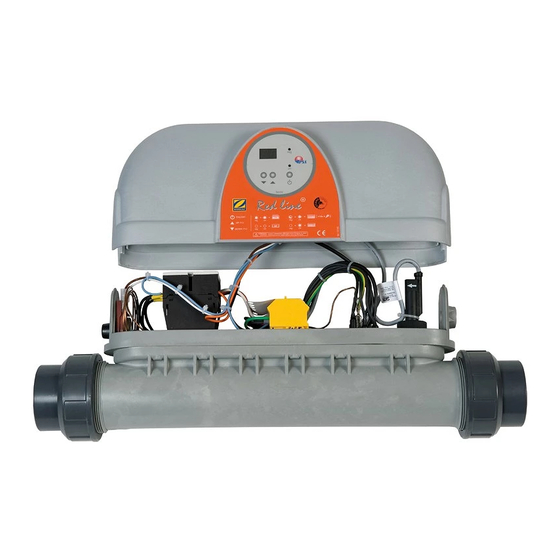
- Page 1 Instructions for installation and use English H03609-00.B - 2012/01...
- Page 2 Read this manual carefully before installing, maintaining or repairing this device! The symbol indicates important information that must be taken into account in order to avoid risk of personal injury and/or damage to the appliance. The symbol indicates useful information. Warnings Our products may be subject to change without notice as part of our continuous improvement policy. Exclusive use: pool water heating (must not be used for any other purpose). The device must be installed by a qualified technician according to the manufacturer’s instructions and in compliance with local regulations. The installer is responsible for the correct installation of the ...
-
Page 3: Table Of Contents
Summary 1. Information before installation ....................... 2 1.1 General terms of delivery, storage and transport ...................... 2 1.2 Content .................................. 2 1.3 Operating conditions .............................. 2 1.4 Technical specifications .............................. 2 2. Installation ............................ 3 2.1 Selecting an installation site ............................ 3 2.2 Hydraulic connections .............................. 3 2.3 Electrical connections .............................. 3 3. Use .............................. 4 3.1 Presentation of the regulation ............................ 4 3.2 Starting the device ................................ 4 3.3 Checks to be carried out after operating for a few moments .................. 5 3.4 Winter storage ................................ 5 4. Maintenance ........................... 5 ... -
Page 4: Installation
2. Installation 2.1 Selecting an installation site The appliance must be installed in a technical room ventilated, dry and without stored pool treatment products. 90° elbow fittings must not be installed directly at the exchanger outlet; leave at least 25 cm of straight pipe to prevent chatter of the flow controller armature. The appliance must be set horizontally or vertically and supported by pipes held in place by fixing clips on either side of the heater, If the heater is installed vertically, the water flow must circulate from bottom to top, The heater must not be installed as below, the flow controller will be triggered: An unobstructed space around the appliance is required to facilitate its installation and maintenance, Preferably, the heater should be installed at the low point so that it is always full of water, The water treatment system must be installed after the exchanger and at a low point to prevent chlorine from returning back into the heater. 2.2 Hydraulic connections Observe the hydraulic connection direction (see arrow on the heater body). ... -
Page 5: Use
Loose terminals may cause the supply terminal board to overheat, and will void the warranty. The device must be connected to an earth electrode. Risk of electric shock inside the device. The device must only be connected by a qualified and experienced technician. If the power cable is damaged, it must be replaced by a qualified technician. Single‐phase Three‐phase Heater terminal strip Shunt Power cable 30 mA differential circuit breaker Phase Neutral Earth 2.3.3 Cable cross‐sections •supply cable cross‐section: cables with a maximum length of 20 metres (calculation base: 5A/mm²), must be checked and adapted depending on installation conditions. ... -
Page 6: Checks To Be Carried Out After Operating For A Few Moments
If the water flow rate is too low (less than 5 m³/h), or if the filtration is stopped, the “reg” indicator light will flash and the heater will stop heating, When the pool has reached the desired temperature, the “reg” indicator light goes out, the heater will stop heating. 3.3 Checks to be carried out after operating for a few moments Check that the heater stops heating when: the setpoint temperature is decreased or when the control is shut off, filtration is switched off. 3.4 Winter storage Winter storage is essential due to the risk of body of the heater freezing and breaking. This situation is not covered by the warranty. Turn off control unit power, Shut off water circulation, Drain the heater : - close valves 2 and 3 (see §2.2), if installed, - unscrew the fittings to drain the heater, - when the heater is empty, lightly retighten the fittings, without creating a seal. 4. Maintenance 4.1 Maintenance instructions ... -
Page 7: Fuse Replacement
keys for 5 seconds. Press to scroll through each parameter until “r2” is displayed. Press , the current value of the parameter “r2” is displayed. Press or to modify the maximum setpoint value. Press to confirm this new value. Simultaneously press and hold and for 5 seconds to return to the pool water temperature display. 6. Product registration Register your product using our website: - you will be among the first to be informed of new Zodiac products and special offers, - You can help us to constantly improve our product quality. Australia – New Zealand www.zodiac.com.au South Africa www.zodiac.co.za Europe and rest of the world www.zodiac‐poolcare.com 7. Conformity certificate Z.P.C.E. declares that the following products or ranges: Special swimming pool heater: Red Line + 3‐6‐9‐12 are in compliance with the provisions of: ... - Page 8 Wiring diagram Red Line 3‐6‐9 kW single‐phase and three‐phase Red Line 12 kW three‐phase 1 H03609‐00.B1.EN – 2012/01...
- Page 9 C‐R power supply 230V‐1N‐50Hz N‐R‐S‐T power supply 400V‐3N‐50Hz TH control thermostat with digital display F1 fuse 3.15 A‐G CD flow controller So pool water control sensor (PTC) R Heating element (power engraved on the metal resistor cup) KM1 power contactor TS safety thermostat positive (triggering at 63°C, manual reset) GN‐GG black or grey sheath CN Black cable with clips of colours V‐j green‐yellow B blue M brown Bl white N black Ro red Vi violet Ground Description ...
- Page 10 Dimensions A B weight Red Line mm mm Kg 3‐6 538 452 3,5 9‐12 638 552 4 3 H03609‐00.B1.EN – 2012/01...
- Page 11 Notes...
- Page 12 Plaque signalétique – Product name plate Votre revendeur / your retailer Pour plus de renseignements, merci de contacter votre revendeur. For further information, please contact your retailer. ZODIAC® is a registered trademark of Zodiac International, S.A.S.U., used under license.
Need help?
Do you have a question about the RED LINE and is the answer not in the manual?
Questions and answers