Zodiac Red Line 3 Installation And User Manual
Hide thumbs
Also See for Red Line 3:
- Instructions for installation and use manual (60 pages) ,
- Instructions for installation and use manual (72 pages) ,
- Instructions for installation and use manual (12 pages)

Subscribe to Our Youtube Channel
Related Manuals for Zodiac Red Line 3


Summary of Contents for Zodiac Red Line 3
- Page 1 Installation and user manual - English Electric heater Translation of the original instructions in French More documents on: www.zodiac.com H0360900_REVC - 2020/02...
- Page 2 WARNINGS GENERAL WARNINGS • Failure to respect the warnings may cause serious damage to the pool equipment or cause serious injury, even death. • Only a person qualified in the technical fields concerned (electricity, hydraulics or refrigeration) is authorised to perform this procedure. The qualified technician working on the appliance must use/wear personal protective equipment (such as safety goggles and protective gloves, etc.) in order to reduce the risk of injury occurring when working on the appliance.
- Page 3 WARNINGS ASSOCIATED WITH ELECTRICAL APPLIANCES • The power supply to the appliance must be protected by a dedicated 30 mA residual current device, complying with the standards and regulations in force in the country in which it is installed. • Do not use any extension lead when connecting the appliance; connect the appliance directly to a suitable power supply.
-
Page 4: Table Of Contents
• The distribution or modification of this document in any way is prohibited, without prior authorisation from Zodiac®. • Zodiac® is constantly developing its products to improve their quality. The information contained herein may therefore be modified without notice. CONTENTS ❶... -
Page 5: ❶ Specifications
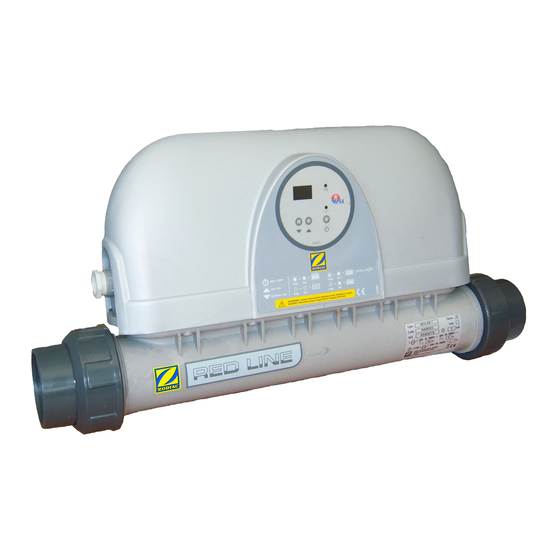
❶ Specifications 1.1 I Description Red Line Ø63 connector (x2) Ø50 connector (x2) Joint (x2) 1.2 I Technical specifications Red Line Unit Power* Power supply 230V single- phase 400V three- phase * with manufacturer tolerance ± 5% • Protection index: IP 45 •... -
Page 6: I Dimensions And Marking
1.3 I Dimensions and marking Regulator Flow switch Gland Heater body ½ union PVC connector Ø63/50 Overheat control Power contactor Supply terminal block Resistor Screw thimble + regulation sensor Screw thimble + safety thermostat sensor Red Line Weight... -
Page 7: ❷ Installation
❷ Installation 2.1 I Selecting the location • The appliance must be installed in a dry ventilated plant room with no pool maintenance products stored nearby. • 90° elbow fittings must not be installed directly at the heater inlet and outlet; leave at least 25 cm of straight pipe to prevent chatter of the flow switch armature. -
Page 8: I Electrical Connections
2.3 I Electrical connections 2.3.1 Voltage and protection • The power supply to the heater must be provided through a protection and circuit breaking device (not supplied) complying with the standards and regulations in force in the country where it is installed, •... -
Page 9: ❸ Use
❸ Use 3.1 I Presentation of the regulation system Press and release Press and hold To confirm a value "On/off" To browse and adjust values To quickly scroll through the values Description Steady Flashing Appliance "On/Off" switched Inactive indicator light On hold Water flow rate too low (less than 5 m³/h) Pool at... -
Page 10: ❹ Maintenance
❹ Maintenance 4.1 I Winterising • Winter storage is essential due to the risk of the heater body freezing and breaking. This is not covered by the warranty. • Switch off the regulation system, • Stop water circulation, • Drain the heater: - Close valves 2 and 3 (see §... -
Page 11: I Wiring Diagram
5.2 I Wiring diagram 5.2.1 Red Line 3-6-9 kW single-phase current and three-phase current 230V-1N-50Hz power supply N-R-S-T 400V-3N-50Hz power supply Regulating thermostat with digital display 3.15 A-T protection fuse Flow switch Pool water regulation sensor (PTC) Resistor (capacity engraved on the metal cup) Power contactor Overheat control (triggered at 63 °C, manual reset) - Page 12 5.2.2 Red Line 12 kW three-phase current 230V-1N-50Hz power supply N-R-S-T 400V-3N-50Hz power supply Regulating thermostat with digital display 3.15 A-T protection fuse Flow switch Pool water regulation sensor (PTC) Resistor (capacity engraved on the metal cup) Power contactor Overheat control (triggered at 63 °C, manual reset) GN-GG Black cladding or grey cladding Black cable (coloured electrical bonding)
- Page 13 Your retailer Modèle appareil Appliance model Numéro de série Serial number Pour plus d’informations, enregistrement produit et support client : For more information, product registration and customer support: www.zodiac.com ZODIAC® is a registered trademark of Zodiac International, S.A.S.U., used under license.
Need help?
Do you have a question about the Red Line 3 and is the answer not in the manual?
Questions and answers