Table of Contents

Related Manuals for CDI TRAXALL 770


Summary of Contents for CDI TRAXALL 770
- Page 1 TRAXALL Multi-source Magnetic Pipeline Pig Location and Tracking System Models 770 & 720 USER GUIDE 1801 North Juniper Avenue Broken Arrow, Oklahoma 74012 U.S.A. +1 (918) 258-6068 worldwide www.pigging.com support@pigging.com...
- Page 2 The software, hardware, and firmware described in this document are designed, manufactured, and written by CDI. The software and firmware copyright © 2014 CDI with all rights reserved. This document © 2014–2017 CDI. All rights reserved.
-
Page 3: Table Of Contents
TRAXALL Firmware ................76 Optional Equipment ................79 TRAXALL Linestat ................. 79 Remote Passage Flasher..............80 Bulkhead-to-Client Device Cable ............80 WARRANTY .................... 81 CARE, MAINTENANCE, & SERVICING ..........82 NOTES ....................83 ABOUT CDI .................... 84 Page 3 of 84... -
Page 4: About This User Guide
TRAXALL 700 SERIES USER GUIDE ABOUT THIS USER GUIDE Conventions used in this publication pq u t indicate you are to press Up, Down, Right, Left, or Enter on the keypad (pg. 10): Menu options will appear in this guide exactly as displayed. For example, “REC PASSES”... -
Page 5: Overview
STARTED and OPERATION sections of this user guide. Details can be found in the APPENDIX (pg. 40). TRAXALL 770 and 720 are identical in design, function, and operation, differing only in multi-frequency capability. The 720 can identify and record two transmitter frequencies simultaneously, the 770 can process as many as seven plus the 22 Hz Legacy frequency. -
Page 6: Devices Supported By Traxall
DEVICES OVERVIEW Devices Supported by TRAXALL Multi-frequency Transmitters The TRAXALL 770 can separate, identify, and record as many as seven transmitter frequencies* simultaneously. Transmission pulse rate of each color-coded CDI X-Series transmitter can be customized with CDI’s special FieldLink Configurator application. - Page 7 TRAXALL 700 SERIES USER GUIDE DEVICES OVERVIEW Magnetic Flux Leakage (MFL) Pigs Magnetic Flux Leakage is a form of nondestructive inline inspection that detects corrosion, pitting, missing metal, cracks, and/or other defects in steel pipelines. An MFL “smart pig” such as shown here is a common inline inspection tool: DETECTOR MAGNETIC POLES...
-
Page 8: Components
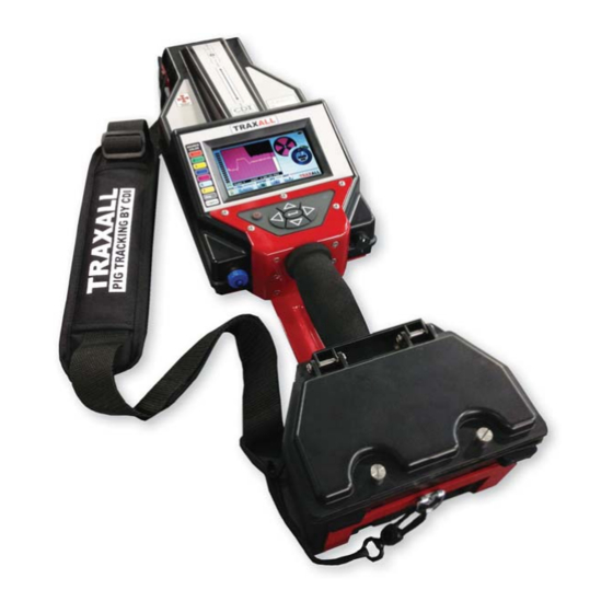
COMPONENTS TRAXALL 700 SERIES USER GUIDE OVERVIEW Components TRANSMITTER AND MFL SENSOR PIPE ALIGNMENT LEGEND PIPE ALIGNMENT LEGEND MFL & TRANSMITTER SENSOR ANTENNAS ANTENNAS LCD DISPLAY MAGNETO-RESITIVE (MR) LCD DISPLAY MAGNETO-RESISTIVE (MR) PINPOINTER SENSOR ARRAY PINPOINTER SENSOR ARRAY CONTROLS CONTROLS SHOULDER SHOULDER STRAP... - Page 9 COMPONENTS/CONTROLS TRAXALL 700 SERIES USER GUIDE OVERVIEW The handle and shoulder strap support the TRAXALL receiver during portable tracking/searching operation, such as “walking a line” during Pinpointing (pg. 33). Page 9 of 84...
-
Page 10: Controls
CONTROLS TRAXALL 700 SERIES USER GUIDE OVERVIEW Controls AUTOMATIC AUTOMATIC LIGHT SENSOR LIGHT SENSOR KEYPAD KEYPAD POWER POWER ON/OFF ON/OFF RELAY PORT RELAY PORT FOR SATELLITE RADIO FOR SATELLITE RADIO & RELAY CONTACTS & RELAY CONTACTS USB/BLUETOOTH CONNECTION CONNECTION Power ON/OFF Depress button for 3–5 seconds to power up the TRAXALL receiver (same to power down). -
Page 11: I/O Connections
I/O CONNECTIONS TRAXALL 700 SERIES USER GUIDE OVERVIEW I/O Connections Relay Port A 12-pin connector provides CDI LineStat satellite radio connection, I/O, and programmable relay contacts which are programmable to varying patterns. When connected to a laptop or PC, TRAXALL will register as a mass storage device on the host PC. -
Page 12: Lcd Display
This is a decal to help you identify signal source displayed in the History Window. 1–7: TRAXALL X-Series transmitters, color-coded across seven different frequencies (Transmitter 1 and 2 for the TRAXALL 720 model) Legacy: Traditional CDI CD42 T-Series single-frequency (22 Hz) transmitters Page 12 of 84... - Page 13 LCD DISPLAY TRAXALL 700 SERIES USER GUIDE OVERVIEW Mag: used to detect a magnetic flux leakage (MFL) “smart pig.” GAIN Control & Indicator to increase/decrease TRAXALL receiver sensitivity. Green/red stack indicates current sensitivity level Usually, advancing gain about 1/3 up the scale –indicated by the stacked green LED array on left–will be adequate to start with.
- Page 14 LCD DISPLAY TRAXALL 700 SERIES USER GUIDE OVERVIEW FILL Menu This is where the transmitter type (or magnetic flux pig) is selected. Use pq to cycle through • AUTO Select – displays all detected transmitters • Manual Select – TRAXALL multi-frequency color-coded transmitters 1–7 •...
- Page 15 TRAXALL 700 SERIES USER GUIDE OVERVIEW The Magnitude History displays pig passages in a right-to-left real time progression which can also be recorded and replayed later. (See pgs. 22- 32.) The dominant (strongest) signal is represented in a solid graph while other signals are shown in outline.
- Page 16 TRAXALL 700 SERIES USER GUIDE OVERVIEW Manual Mode If Fill 1 through 7* or Legacy are selected, TRAXALL will detect and display all active electromagnetic transmitters within range just as with Auto mode, but display priority will be given to transmitter selected, regardless of signal stength.
- Page 17 LCD DISPLAY TRAXALL 700 SERIES USER GUIDE OVERVIEW MAG Mode This is for detecting Magnetic-flux leakage (MFL) “smart pigs” that are not equipped with electromagnetic tranmitters. (See pg. 29) SYSTEM Menu Use the SYSTEM menu to • Set up a recording method •...
- Page 18 TRAXALL 700 SERIES USER GUIDE OVERVIEW HELP Menu About TRAXALL displays your TRAXALL’s serial number, firmware version, CDI contact information, and system free storage capacity. (You may need this information should you contact CDI for operational or service-related questions.) DISPLAY LEGEND is a handy quick- reference to LCD controls and indicators.
-
Page 19: Getting Started
UNPACKING/BATTERIES TRAXALL 700 SERIES USER GUIDE GETTING STARTED GETTING STARTED Unpacking The TRAXALL is shipped preassembled. It is only necessary to insert the batteries (included). Batteries Open the TRAXALL battery compartment. A screwdriver is included for this purpose. D-cell batteries are also included. Insert six–positive side to contacts–as shown here. - Page 20 STARTUP TRAXALL 700 SERIES USER GUIDE GETTING STARTED Close the compartment. Make sure screws are firmly seated to maintain a weatherproof seal. Startup Hold down the Power button about 3–5 seconds. TRAXALL firmware and serial number will momentarily appear. (This information is also available in the HELP menu. See pg. 18.) Page 20 of 84...
-
Page 21: Operation
TRACKING TRAXALL 700 SERIES USER GUIDE OPERATION OPERATION Passage Detection Using your TRAXALL to detect and record data for a moving pig, and/or confirm successful launch and recovery. Align the TRAXALL along pipeline as shown. Position TRAXALL on a pig trap to confirm pig has cleared a valve. -
Page 22: Record/Playback
TRACKING TRAXALL 700 SERIES USER GUIDE OPERATION Record mode and job assignment You may monitor in real time, record, or monitor and record depending on how you configure the REC PASSES options in the SYSTEM menu. From the SYSTEM menu o record: –... - Page 23 TRACKING TRAXALL 700 SERIES USER GUIDE OPERATION AUTO TRIGGER mode keeps TRAXALL in a passive state until a passage Waiting for Trigger is detected. (Note prompt.) AUTO TRIGGER will record ten passage events per job folder. MANUAL begins data logging as soon as selected. “Logging Data” will appear in red.
- Page 24 TRAXALL 700 SERIES USER GUIDE OPERATION Tracking Example 1 Here are some typical tracking applications: SETTINGS: Transmitter: CDI X100 Fill setting: AUTO Record mode: AUTO TRIGGER Once settings are entered, your TRAXALL is ready to record a passage. Page 24 of 84...
- Page 25 TRACKING TRAXALL 700 SERIES USER GUIDE OPERATION Waiting for Trigger As you are in AUTO TRIGGER, TRAXALL will remain in a wait-state until a pig transmitter reaches the sensor antenna Verifying Passage The pig has passed through this location, and TRAXALL is now verifying and logging passage Passage Logged TRAXALL is writing passage information to the Job 1 folder of system...
- Page 26 TRACKING TRAXALL 700 SERIES USER GUIDE OPERATION Playback Replay recorded passes by accessing the log files as shown here. Use upq to access the desired Job folder and log file. From VIEW, use u to replay, or q to delete. NOTE: You may pause (freeze) data display by q while SYSTEM is highlighted.
- Page 27 TRACKING TRAXALL 700 SERIES USER GUIDE OPERATION Playback (cont.) Viewing a recorded logfile works in the same manner as a video player. Use the arrow keys to control playback: Forward/Reverse Increase replay speed Decrease replay speed Pause Unpause Stop When log file is replayed the graphic timeline will scroll from right to left.
- Page 28 TRACKING TRAXALL 700 SERIES USER GUIDE OPERATION Playback (cont.) Recorded passage is indicated by graph peak. Note Pinpointer is also confirming passage (see pg. 33). Reappearance of the BOF marker indicates conclusion of log file which will continually loop until stopped. Recorded passage can be viewed in TRANS HISTORY (default) or AXIS HISTORY modes.
- Page 29 TRACKING TRAXALL 700 SERIES USER GUIDE OPERATION Tracking Example 2 SETTINGS: Pig: Magnetic Flux Leakage (MFL) Fill setting: Record mode: Manual NOTE: Unless the MFL tool is configured with an ILI transmitter,* Fill mode must be set to Mag when manually tracking/recording magnetic flux leakage devices.
- Page 30 TRACKING TRAXALL 700 SERIES USER GUIDE OPERATION TRAXALL will continually write passage data to the logfile until REC PASSES is unchecked. Playback Replay recorded passes in the same manner as Job 1 (pg. 24). TRANS HISTORY AXIS HISTORY Page 30 of 84...
- Page 31 TRACKING TRAXALL 700 SERIES USER GUIDE OPERATION Tracking Example 3 SETTINGS: Transmitter: CD42-T0 Fill setting: Legacy Record mode: Auto Waiting for Trigger As you are in AUTO TRIGGER, TRAXALL will remain in a wait-state until a pig transmitter reaches the sensor antenna Verifying Passage The pig has passed through this location, and TRAXALL is now verifying and logging passage...
- Page 32 TRACKING TRAXALL 700 SERIES USER GUIDE OPERATION Passage Logged TRAXALL is writing passage information to the Job 1 folder of system memory. (You may review this passage at any time via VIEW REC LIST menu.) TRAXALL is ready for the next passage. Playback Replay recorded passes in the same manner as Job 1 (pg.
-
Page 33: Pinpointing
Known: pipeline last recorded position (“A”) flow direction (“A” to “B”) transmitter type (CDI X100) Unknown: present location of obstructed pig *MFL pigs are not located with the Pinpointer; rather, you use the tracking capability to locate the magnetic passage detection (see Tracking Example 2, pg. - Page 34 PINPOINTING TRAXALL 700 SERIES USER GUIDE OPERATION “Walking a Line” (X100 transmitter shown) Pinpointing is similar to passage detection except there will likely be no need for recording, as pinpointing is a “hands on” operation. From last known position, proceed downline, keeping TRAXALL as closely aligned with pipeline as practical.
- Page 35 PINPOINTING TRAXALL 700 SERIES USER GUIDE OPERATION “Walking a Line” (cont.) When you have passed the transmitter, turn and retrace your steps back toward the transmitter while watching the Pinpointer dial. The four “pie wedge” shaped markers in the dial function as precision sighting cross hairs.
- Page 36 PINPOINTING TRAXALL 700 SERIES USER GUIDE OPERATION “Walking a Line” (cont.) The markers will continue to increase in size as you reach the transmitter. Page 36 of 84...
- Page 37 PINPOINTING TRAXALL 700 SERIES USER GUIDE OPERATION Here, your TRAXALL’s pinpoint MR sensor is directly over the X100 magnetic null zone. The pinpointer markers are full size and outlined. You have located the X100 transmitter! Page 37 of 84...
- Page 38 PINPOINTING TRAXALL 700 SERIES USER GUIDE OPERATION “Walking the Line” (Legacy Transmitter firmware < V0.0096) If your TRAXALL firmware release version is prior to V0.0096,* the upper and lower markers will decrease in size as you re-approach a 22 Hz single-frequency (legacy) transmitter.
- Page 39 PINPOINTING TRAXALL 700 SERIES USER GUIDE OPERATION Note peak in History Window graph, and diminished vertical pinpointer markers. Both indicate that the TRAXALL is over the magnetic “null” zone of a legacy transmitter. Page 39 of 84...
-
Page 40: Appendices
SYSTEM MENU TRAXALL 700 SERIES USER GUIDE APPENDIX APPENDIX System Menu Tree Relay Options Set up and program the two RELAYS for various pulse train behavior. The relay contacts can be used for passage annunciation (lights, horns, etc.), a very useful feature where an unmanned passage must be monitored. - Page 41 SYSTEM MENU TRAXALL 700 SERIES USER GUIDE APPENDIX Relay Options (cont.) CYCLES can be set for 1 to 10 relay repetitions. When LATCH* is checked, relay will stay tripped until RESET is selected. Example: if NORMALY OPEN is checked, the relay will close when activated by passage, and stay closed until reset.
- Page 42 SYSTEM MENU TRAXALL 700 SERIES USER GUIDE APPENDIX Data Win View DATA WIN VIEW offers three ways of graphing transmitter passage. TRANS HISTORY is the default data display mode. It is an X–Y graph, where X=Time and Y=Signal Magnitude. When TRAXALL is set to TRANS HISTORY, passage data can be viewed in real time, or, if recorded, the log file can be replayed at a later time.
- Page 43 SYSTEM MENU TRAXALL 700 SERIES USER GUIDE APPENDIX Data Win View (continued) TRANS FFT (Fast Fourier transform), or Spectral mode, is a time-to-frequency conversion algorithm where X=Signal Frequency and Y = Signal Magnitude. When TRAXALL is set to TRANS FFT, passage data can be viewed in real time only.
- Page 44 TRAXALL 700 SERIES USER GUIDE APPENDIX The FFT view mode can also be used to survey a tracking environment for ambient electromagnetic noise. Ambient noise is electromagnetic activity which could be misinterpreted as a passage. Sources can include power lines, machinery, and passing motor vehicles or railroad trains. Here, the white graph line represents signals detected across an electromagnetic spectrum including the TRAXALL transmitter range(17.5 to 29.29 Hz).
- Page 45 TRAXALL 700 SERIES USER GUIDE SYSTEM MENU APPENDIX Data Win View (continued) AXIS HISTORY plots a signal’s relative field magnitude where red = X, green = Y, and blue = Z. When TRAXALL is set to AXIS HISTORY, passage data can be viewed in real time, or, if recorded, the log file can be...
- Page 46 SYSTEM MENU TRAXALL 700 SERIES USER GUIDE APPENDIX Set GMT Offset This menu sets TRAXALL to your local Time Zone and/or Daylight Savings Time (DST). With SET GMT OFFSET highlighted, u to highlight GMT OFFSET, then u again (GMT OFFSET text will turn red). Default is 0.
- Page 47 SYSTEM MENU APPENDIX TRAXALL 700 SERIES USER GUIDE Backlight Adjustment TRAXALL LCD brightness is automatically adjusted for optimal visibility and battery life by the built-in Automatic Light Sensor (ALS). The LCD will also “go blank” (turn off) after one minute of non-use. But you can override the ALS by controlling both brightness and blanking intervals through this menu.
-
Page 48: Global Positioning System (Gps)
GPS MENU TRAXALL 700 SERIES USER GUIDE APPENDIX Global Positioning System (GPS) TRAXALL’s fully-functional GPS receiver provide precise timing for benchmarking passage events. The TRAXALL position is updated five times per second. The GPS almanac and real-time clock are on battery backup while TRAXALL is off. - Page 49 GPS MENU TRAXALL 700 SERIES USER GUIDE APPENDIX GPS Setup and Operation From the GPS menu, use pq to access GPS On/Off checkbox, then u to check. This will enable the GPS. Once enabled, it will begin searching for GPS satellites. When three satellites are acquired, the signal strength indicator bars will change “GOLF TEE”...
- Page 50 GPS MENU TRAXALL 700 SERIES USER GUIDE APPENDIX GPS Setup and Operation When you have selected a function, you will be prompted to assign your task to one of five Job folders. The Job folders are where waypoint (*.wpt) and tracking (*.nmea) files are stored.
- Page 51 GPS MENU TRAXALL 700 SERIES USER GUIDE APPENDIX GPS Setup and Operation (cont.) SELect VISIBLE DATA to choose either CLOSING DISTance, ALTITUDE, or GROUND SPEED values in the range portion of the GPS dial. Page 51 of 84...
- Page 52 GPS MENU TRAXALL 700 SERIES USER GUIDE APPENDIX Setting Waypoints Waypoints record GPS latitude and longitude data at the current Traxall position. They can be saved provided the GPS signal strength indicator has three or more bars. (Waypoint data is most accurate if four bars are present.) While Waypoints can be set anywhere, they are usually features or landmarks directly related to pipeline pigging operations;...
- Page 53 GPS MENU TRAXALL 700 SERIES USER GUIDE APPENDIX Waypoints are stored in the Job folders as *.wpt files. Each waypoint file contains • Date • Time • Latitude • Longitude • Elevation Once set, recorded waypoints may be displayed, navigated to, or deleted.
- Page 54 GPS TRACKING TRAXALL 700 SERIES USER GUIDE APPENDIX Recording Tracks In addition to storing waypoints, you may record an entire traverse for later viewing and analysis in Google Earth. Track recording may be done along with other TRAXALL operations such as passage detection and/or pinpointing.
- Page 55 GPS & MAPPING TRAXALL 700 SERIES USER GUIDE APPENDIX Downloading to Google Earth After recording your track(s), connect TRAXALL to a laptop or PC. When connected, TRAXALL will register as a mass storage device. Open Google Earth on your laptop/PC, and “drag and drop” an NMEA file from the file list over to the Google Earth application.
-
Page 56: Remote Operation
TRAXALL 700 SERIES USER GUIDE TRAXALL REMOTE CONTROL APPENDIX Remote Operation TRAXALL Remote Control is a Windows application that will let you monitor and operate your TRAXALL receiver from a remote location (for example, a vehicle cab or shelter during inclement weather) on a laptop or PC. - Page 57 TRAXALL 700 SERIES USER GUIDE TRAXALL REMOTE CONTROL APPENDIX START BLUETOOTH From your TRAXALL receiver SYSTEM menu, highlight BLUETOOTH option key to enable Bluetooth communication. and select Enter grey blue* to confirm. The Bluetooth icon will change from GREY = Bluetooth disabled BLUE = Bluetooth enabled GREEN...
- Page 58 PC or laptop and then launch the TRAXALL Remote Control application. (See following pages.) NOTE: only Microsoft Bluetooth drivers are supported by TRAXALL. Contact CDI support@pigging.com or 1-800-580-4234 if you require Bluetooth connectivity assistance. Page 58 of 84...
- Page 59 A USB Micro Bluetooth Adapter (“dongle”) is included with your TRAXALL. Insert adapter into your PC or laptop USB port as shown here. Contact CDI support@pigging.com or 1-800-580-4234 to obtain and install TRAXALL Remote Control to your PC. CDI Part # 81-03-0041-00 If your PC has built-in Bluetooth, it will be necessary to disable it via Windows Device Manager.
- Page 60 TRAXALL 700 SERIES USER GUIDE TRAXALL REMOTE CONTROL APPENDIX Launch TRAXALL Remote Control (cont.) Click the TRAXALL Remote Control application icon on your PC desktop. Page 60 of 84...
- Page 61 TRAXALL 700 SERIES USER GUIDE TRAXALL REMOTE CONTROL APPENDIX The TRAXALL Remote Control application will open. Page 61 of 84...
- Page 62 TRAXALL 700 SERIES USER GUIDE TRAXALL REMOTE CONTROL APPENDIX SELECT DEVICE Click on the Select Device button to open the Device Survey Window The Device Survey Window will display all previously-paired TRAXALL devices If your device is not listed, you will need to pair it through the Windows Bluetooth settings application.
- Page 63 TRAXALL 700 SERIES USER GUIDE TRAXALL REMOTE CONTROL APPENDIX “Clock” icon indicates that TRAXALL Remote Control is verifying connectivity for a TRAXALL unit. Green check mark icon indicates TRAXALL unit or units are configured for use on your PC. Warning icon indicates the TRAXALL unit is not communicating with TRAXALL Remote Control.
- Page 64 TRAXALL 700 SERIES USER GUIDE TRAXALL REMOTE CONTROL APPENDIX Select Device (cont.) When prompted, enter a pairing code for the TRAXALL. The pairing code will be the last four numbers of your TRAXALL’s serial number. NOTE: This screen will vary depending upon your version of Windows. The serial number may be accessed via the TRAXALL HELP menu.
- Page 65 TRAXALL 700 SERIES USER GUIDE TRAXALL REMOTE CONTROL APPENDIX Select desired device. Click OK button to begin connection. Page 65 of 84...
- Page 66 TRAXALL 700 SERIES USER GUIDE TRAXALL REMOTE CONTROL APPENDIX Select Device (cont.) When communication is established, the Bluetooth icon will change blue to green.* from GREY = Bluetooth disabled BLUE = Bluetooth enabled GREEN = Bluetooth connected Page 66 of 84...
- Page 67 TRAXALL 700 SERIES USER GUIDE TRAXALL REMOTE CONTROL APPENDIX LINK DEVICE If the TRAXALL Remote Control application window on your PC shows TRAXALL activity you have communication. Page 67 of 84...
- Page 68 TRAXALL 700 SERIES USER GUIDE TRAXALL REMOTE CONTROL APPENDIX OPERATE TRAXALL REMOTE CONTROL TRAXALL Remote Control functions can be accessed by menus, icons, and/or tabs. MENU OPTIONS MENU OPTIONS File Save Saves text in Log Window to a file Exit Closes the TRAXALL Remote Control application View Tool Bar...
- Page 69 TRAXALL 700 SERIES USER GUIDE TRAXALL REMOTE CONTROL APPENDIX MENU OPTIONS TRAXALL Reset Sensor Restores MR sensor sensitivity* Transport Live Pause Stop These commands control History Window data stream from TRAXALL receiver. They do not control TRAXALL functions, but control only the real-time display seen at the PC end. Gain Controls TRAXALL receiver sensitivity.
- Page 70 TRAXALL 700 SERIES USER GUIDE TRAXALL REMOTE CONTROL APPENDIX Operate TRAXALL Remote Control (cont.). HISTORY WINDOW TOOL BAR GAIN STRENGTH INDICATOR GAIN PASSAGE CONTROL PROMPT TRANSMITTER SELECTOR MANUAL RECORD CONTROL DATA STREAM CONTROLS Page 70 of 84...
- Page 71 TRAXALL 700 SERIES USER GUIDE TRAXALL REMOTE CONTROL APPENDIX TOOL BAR Bluetooth Wizard Connect Disconnect HISTORY WINDOW Real-time graphic plot of transmitter passage PASSAGE PROMPT When TRAXALL receiver is recording, these prompts will show in successive order Waiting for Trigger. Verifying Passage Logging Data MANUAL RECORD CONTROL...
- Page 72 TRAXALL 700 SERIES USER GUIDE TRAXALL REMOTE CONTROL APPENDIX Operate TRAXALL Remote Control (cont.). INFO DISPLAY TABS INFO DISPLAY WINDOW CLEAR BUTTON PASSAGE & EVENT COUNTERS Page 72 of 84...
- Page 73 TRAXALL 700 SERIES USER GUIDE TRAXALL REMOTE CONTROL APPENDIX INFO DISPLAY WINDOW & TABS Choose between: Tracking information in text format Axis History Real-time plots of signal relative field magnitude where red = X, green = Y, and blue = Z Device Info TRAXALL unit and GPS information Passage and Event Counters...
- Page 74 TRAXALL 700 SERIES USER GUIDE TRAXALL REMOTE CONTROL APPENDIX Operate TRAXALL Remote Control (cont.). STATUS BAR TIME APPLICATION SIGNAL STRENGTH STATUS CONNECTION STATUS BATTERY STATUS Page 74 of 84...
- Page 75 TRAXALL 700 SERIES USER GUIDE TRAXALL REMOTE CONTROL APPENDIX STATUS BAR Application Status Displays current state of TRAXALL Remote Control application Connection Status Color = connected; Grey = disconnected Battery TRAXALL battery charge status Signal Strength TRAXALL-PC Bluetooth link Time Local time-of-day Page 75 of 84...
-
Page 76: Traxall Firmware
HELP menu, then About TRAXALL 770. Firmware Release V.0070-0082 A firmware release of V.0082 or older will require an upgrade at CDI. Contact CDI at 1-800-580-4234, ext 143 for CDI RMA Form FM-03-0089. Firmware Release V.0083 and Newer A firmware release of V.0083 or newer can be upgraded by uploading... - Page 77 FIRMWARE TRAXALL 700 SERIES USER GUIDE APPENDIX Firmware Release V.0083 and Newer (continued) To upload and install this file to your Traxall: POWER UP TRAXALL CONNECT TRAXALL TO PC Windows AutoPlay window will indicate the TRAXALL as a Mass Storage Device and assign the next available drive letter to it.
- Page 78 The screen will remain white/light grey for about three minutes, then shut down. RESTART TRAXALL AGAIN Verify the new version is displayed in startup screen. The Firmware update is now complete. Contact CDI support@pigging.com or 1-800-580-4234 if you require Firmware upgrade assistance. Page 78 of 84...
-
Page 79: Optional Equipment
OPTIONS TRAXALL 700 SERIES USER GUIDE APPENDIX OPTIONAL EQUIPMENT TRAXALL LineStat CDI’s LineStat radio system provides your TRAXALL 770/720 with the ability to autonomously monitor pig passages and send remote notifications as emails or text messages. SAMPLE DATA MESSAGE GLOBALSTAR... -
Page 80: Remote Passage Flasher
CDI Part # 81-05-0130-00 Bulkhead-to-Client Device Cable Special cable for connection of a user-provided device to the TRAXALL 720 or 770 Programmable Relay Port. Typical devices include lights,... -
Page 81: Warranty
Upon receipt of the equipment and Purchase Order, CDI will examine the equipment and make a determination of the nature and cause of the defect. If the defect is not covered by the warranty, CDI will quote to Purchaser the cost for replacement or repair equipment, and will not proceed until Purchaser delivers a written acceptance of the quotation. -
Page 82: Care, Maintenance, & Servicing
Failure to perform these operations nullifies this warranty. CDI equipment should only be operated by qualified personnel who are familiar with any and all manuals and procedures for said equipment’s operation. -
Page 83: Notes
TRAXALL 700 SERIES USER GUIDE NOTES Page 83 of 84... -
Page 84: About Cdi
Oklahoma, just 12 miles from downtown Tulsa. Incorporated in 1982, CDI has proudly been manufacturing products in the United States for more than 32 years. CDI currently employs 45 people in the areas of electronics and mechanical design, software and firmware programming, electronics manufacture, machining, and more.
Need help?
Do you have a question about the TRAXALL 770 and is the answer not in the manual?
Questions and answers