Table of Contents

Related Manuals for CDI TRAXALL 770


Summary of Contents for CDI TRAXALL 770
- Page 1 TRAXALL Mul -source Magne c Pipeline Pig Loca on and Tracking System Pi li Pi L Models 770 & 720 USER GUIDE 1801 North Juniper Avenue Broken Arrow, Oklahoma 74012 U.S.A. +1 (918) 258–6068 worldwide www.pigging.com support@pigging.com...
- Page 2 The so ware, hardware, and fi rmware described in this document are designed, manufactured, and wri en by CDI. The so ware and fi rmware copyright © 2014 CDI with all rights reserved. This document © 2015 CDI. All rights reserved.
-
Page 3: Table Of Contents
System Menu Tree ................38 Global Posi oning System (GPS) ............45 Remote Opera on ................53 OPTIONAL EQUIPMENT ............... 68 TRAXALL Linestat .................. 68 WARRANTY .................... 70 CARE, MAINTENANCE, & SERVICING ..........71 ABOUT CDI .................... 72 Page 3 of 72... -
Page 4: About This User Guide
TRAXALL 700 SERIES USER GUIDE ABOUT THIS USER GUIDE Conven ons used in this publica on indicate you are to press Up, Down, Right, Le , or Enter on the keypad (pg. 10): Menu op ons will appear in this guide exactly as displayed. -
Page 5: Overview
STARTED and OPERATION sec ons of this user guide. Details can be found in the APPENDIX (pg. 38). * TRAXALL 770 and 720 are iden cal in design, func on, and opera on, diff ering only in mul -frequency capability. The 720 can iden fy and record two transmi er frequencies simultaneously, the 770 can process as many as seven. -
Page 6: Devices Supported By Traxall
WARNING Always use cau on when opening any CDI transmi er that has been in a pressurized environment. It is possible for pressurized liquid or gas to leak into a transmi er and remain there even a er the transmi er has been removed from the pipeline. - Page 7 DEVICES OVERVIEW TRAXALL 700 SERIES USER GUIDE Magne c Flux Leakage (MFL) Pigs Magne c Flux Leakage is a form of nondestruc ve inline inspec on that detects corrosion, pi ng, missing metal, cracks, and/or other defects in steel pipelines. An MFL “smart pig”...
-
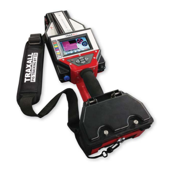
Page 8: Components
COMPONENTS OVERVIEW TRAXALL 700 SERIES USER GUIDE Components PIPE ALIGNMENT LEGEND MFL & TRANSMITTER SENSOR ANTENNAS LCD DISPLAY MAGNETO-RESISTIVE (MR) PINPOINTER SENSOR ARRAY CONTROLS SHOULDER STRAP HANDLE BATTERY COMPARTMENT The Pipe Alignment legend is a guide to help you posi on your TRAXALL receiver for best passage detec on results. -
Page 9: Controls
OVERVIEW TRAXALL 700 SERIES USER GUIDE COMPONENTS/CONTROLS The handle and shoulder strap support the TRAXALL receiver during portable tracking/searching opera on, such as “walking the line” during Pinpoin ng (pg. 31). Controls Power ON/OFF AUTOMATIC LIGHT SENSOR KEYPAD POWER ON/OFF RELAY PORT FOR SATELLITE RADIO &... - Page 10 CONTROLS OVERVIEW TRAXALL 700 SERIES USER GUIDE Depress bu on for 3–5 seconds to power up the TRAXALL receiver (same to power down). Automa c Light Sensor (ALS) The ALS will automa cally adjust LCD backligh ng brightness for op mal visibility and ba ery life.
-
Page 11: I/O Connec Ons
OVERVIEW TRAXALL 700 SERIES USER GUIDE I/O CONNECTIONS I/O Connec ons Relay Port A 12-pin connector provides CDI LineStat satellite radio connec on, I/O, and programmable relay contacts which are programmable to varying pa erns. When connected to a laptop or PC, TRAXALL will register as a mass storage device on the host PC. -
Page 12: Lcd Display
1–7: TRAXALL X-Series transmi ers, color-coded across seven diff erent frequencies (two for the TRAXALL 720 model) Legacy: Tradi onal CDI CD42 T-Series single-frequency (22 Hz) transmi ers Mag: used to detect a magne c fl ux leakage x leakage eakage (MFL) “smart pig”... - Page 13 OVERVIEW TRAXALL 700 SERIES USER GUIDE LCD DISPLAY GAIN Control & Indicator to increase/decrease TRAXALL receiver sensi vity. Green/red LED stack indicates current sensi vity level Usually, advancing gain about 1/3 up the scale –indicated by the stacked green LED array on le –will be adequate to start with.
- Page 14 OVERVIEW TRAXALL 700 SERIES USER GUIDE LCD DISPLAY FILL Menu This is where the transmi er type (or magne c fl ux pig) is selected. Use to cycle through • AUTO • Mul -frequency (color-coded transmi er 1–7) • Mag (MFL) •...
- Page 15 OVERVIEW TRAXALL 700 SERIES USER GUIDE LCD DISPLAY SYSTEM Menu Use the SYSTEM menu to • Set up a recording method • Manage job lists • Enable Bluetooth communica on • Program the relays • Select transmi er history display (graph, FFT, or axis) •...
- Page 16 fi rmware version, CDI contact informa on, and system free storage capacity. (You may need this informa on should you contact CDI for opera onal or service-related ques ons.) DISPLAY LEGEND is a handy quick- reference to LCD controls and indicators.
-
Page 17: Getting Started
UNPACKING/BATTERIES GETTING STARTED TRAXALL 700 SERIES USER GUIDE GETTING STARTED Unpacking The TRAXALL is shipped preassembled. It is only necessary to insert the ba eries (included). Ba eries Open the TRAXALL ba ery compartment. A screwdriver is included for this purpose. D-cell ba eries are also included. - Page 18 GETTING STARTED TRAXALL 700 SERIES USER GUIDE STARTUP Close the compartment. Make sure screws are fi rmly seated to maintain a weatherproof seal. Startup Hold down the Power bu on about 3–5 seconds. TRAXALL fi rmware and serial number will momentarily appear. (This informa on is also available in the HELP menu.
-
Page 19: Operation
TRACKING OPERATION TRAXALL 700 SERIES USER GUIDE OPERATION Passage Detec on Using your TRAXALL to detect and record data for a moving pig. Align the TRAXALL along pipeline as shown. Page 19 of 72... - Page 20 TRACKING OPERATION TRAXALL 700 SERIES USER GUIDE Record mode and job assignment You may monitor in real me, record, or monitor and record depending on how you confi gure the REC PASSES op ons in the SYSTEM menu. From the SYSTEM menu From the SYSTEM menu o record: –...
- Page 21 TRACKING OPERATION TRAXALL 700 SERIES USER GUIDE AUTO TRIGGER mode keeps TRAXALL in a passive state un l a passage is detected. (Note Wai ng for Trigger prompt.) AUTO TRIGGER will record mul ple passages un l the Job folder memory is full.
- Page 22 TRACKING Tracking Example 1 Here are some typical tracking applica ons: SETTINGS: Transmi er: CDI X100 Fill se ng: AUTO Record mode: AUTO TRIGGER Once se ngs are entered, your TRAXALL is ready to record a passage. Page 22 of 72...
- Page 23 TRACKING OPERATION TRAXALL 700 SERIES USER GUIDE Wai ng for Trigger As you are in AUTO TRIGGER, TRAXALL will remain in a wait-state un l a pig transmi er reaches the sensor antenna Verifying Passage The pig has passed through this loca on, and TRAXALL is now verifying and logging passage Passage Logged TRAXALL is wri ng passage informa on to the Job 1 folder of system...
-
Page 24: Playback
TRACKING OPERATION TRAXALL 700 SERIES USER GUIDE Playback Replay recorded passes by accessing the log fi les as shown here. Use to access the desired Job folder and log fi le. From VIEW, use to replay, or to delete. - Page 25 TRACKING OPERATION TRAXALL 700 SERIES USER GUIDE Playback (cont.) Viewing a recorded logfi le works in the same manner as a video player. Use the arrow keys to control playback: Forward/Reverse Increase replay speed Decrease replay speed ...
- Page 26 TRACKING OPERATION TRAXALL 700 SERIES USER GUIDE Playback (cont.) Recorded passage is indicated by graph peak. Note Pinpointer is also confi rming passage (see pg. 31). Reappearance of the BOF marker indicates conclusion of log fi le which will con nually loop un l stopped.
- Page 27 TRACKING OPERATION TRAXALL 700 SERIES USER GUIDE Tracking Example 2 SETTINGS: Pig: Magne c Flux Leakage (MFL) Fill se ng: Record mode: Manual NOTE: Unless the MFL tool is confi gured with an ILI transmi er,* Fill mode must be set to Mag or Legacy when manually tracking/recording magne c fl...
- Page 28 OPERATION TRAXALL 700 SERIES USER GUIDE TRACKING TRAXALL will con nually write passage data to the logfi le un l REC PASSES is unchecked. Playback Replay recorded passes in the same manner as Job 1 (pgs. 22–26). TRANS HISTORY AXIS HISTORY Page 28 of 72...
- Page 29 OPERATION TRAXALL 700 SERIES USER GUIDE TRACKING Tracking Example 3 SETTINGS: Transmi er: CD42-T0 Fill se ng: Legacy Record mode: Auto NOTE: Fill mode must be set to Mag or Legacy when manually tracking/recording 22 Hz single-frequency transmi ers. Wai ng for Trigger As you are in AUTO TRIGGER, TRAXALL will remain in a wait-state un l a pig transmi er reaches the sensor antenna Verifying Passage...
- Page 30 OPERATION TRAXALL 700 SERIES USER GUIDE TRACKING Passage Logged TRAXALL is wri ng passage informa on to the Job 1 folder of system memory. (You may review this passage at any me via VIEW REC LIST menu.) TRAXALL is ready for the next passage. Playback Replay recorded passes in the same manner as Job 1 (pgs.
-
Page 31: Pinpoin Ng
OPERATION TRAXALL 700 SERIES USER GUIDE PINPOINTING Pinpoin ng Using your TRAXALL to fi nd a sta onary pig. The Pinpointer will help you fi nd CDI X-Series es s or “Legacy” transmi ers.* Known: pipeline last recorded posi on (“A”) fl... - Page 32 PINPOINTING OPERATION TRAXALL 700 SERIES USER GUIDE “Walking the Line” (X100 transmi er) Pinpoin ng is similar to passage detec on except there will likely be no need for recording, as pinpoin ng is a “hands on” opera on. From last known posi on, proceed downline, keeping TRAXALL as closely aligned with pipeline as prac cal.
- Page 33 PINPOINTING OPERATION TRAXALL 700 SERIES USER GUIDE “Walking the Line” (cont.) When you have passed the transmi er, turn and retrace your steps back toward the transmi er while watching the Pinpointer dial. The four “pie wedge” shaped markers in the dial func on as precision sigh ng cross hairs.
- Page 34 PINPOINTING OPERATION TRAXALL 700 SERIES USER GUIDE “Walking the Line” (cont.) The markers will con nue to increase in size as you reach the transmi er. Page 34 of 72...
- Page 35 PINPOINTING OPERATION TRAXALL 700 SERIES USER GUIDE Here, your TRAXALL’s pinpoint MR sensor is directly over the X100 magne c null zone. The pinpointer markers are full size and outlined. You have located the X100 transmi er! Page 35 of 72...
- Page 36 PINPOINTING OPERATION TRAXALL 700 SERIES USER GUIDE “Walking the Line” (Legacy Transmi er) Pinpoint a 22 Hz single-frequency transmi er the same way you would an X100, with this excep on: the upper and lower markers will decrease in size as you re-approach the transmi er. Page 36 of 72...
- Page 37 PINPOINTING OPERATION TRAXALL 700 SERIES USER GUIDE Note dip in History Window graph, and diminished pinpointer markers. Both indicate that the TRAXALL is over the magne c “null” zone of a legacy transmi er. Page 37 of 72...
-
Page 38: Appendix
SYSTEM MENU APPENDIX TRAXALL 700 SERIES USER GUIDE APPENDIX System Menu Tree Relay Op ons Set up and program the two RELAYS for various pulse train behavior. The relay contacts can be used for passage annuncia on (lights, horns, etc.), a very useful feature where an unmanned passage must be monitored. - Page 39 SYSTEM MENU APPENDIX TRAXALL 700 SERIES USER GUIDE Relay Op ons (cont.) Set CYCLES for desired number of relay repe ons. RESET deac vates a triggered relay. (It does not change relay se ngs.) Page 39 of 72...
- Page 40 APPENDIX TRAXALL 700 SERIES USER GUIDE SYSTEM MENU Data Win View DATA WIN VIEW off ers three ways of graphing transmi er passage. TRANS HISTORY is the default data display mode. It is an X–Y graph, where X=Time and Y=Signal Magnitude. When TRAXALL is set to TRANS HISTORY, passage data can be viewed in real me, or, if recorded, the log fi...
- Page 41 APPENDIX TRAXALL 700 SERIES USER GUIDE SYSTEM MENU Data Win View (con nued) TRANS FFT (Fast Fourier transform) is a me-to-frequency conversion algorithm where X=Signal Frequency and Y = Signal Magnitude. When TRAXALL is set to TRANS FFT, passage data can be viewed in real me only.
- Page 42 SYSTEM MENU APPENDIX TRAXALL 700 SERIES USER GUIDE Data Win View (con nued) AXIS HISTORY plots a signal’s rela ve fi eld magnitude where red = X, green = Y, and blue = Z. When TRAXALL is set to AXIS HISTORY, passage data can be viewed in real me, or, if recorded, the log fi...
- Page 43 SYSTEM MENU APPENDIX TRAXALL 700 SERIES USER GUIDE Set GMT Off set This menu sets TRAXALL to your local Time Zone and/or Daylight Savings Time (DST). With SET GMT OFFSET highlighted, to highlight GMT OFFSET, then again (GMT OFFSET text will turn red). Default is 0.
- Page 44 APPENDIX TRAXALL 700 SERIES USER GUIDE SYSTEM MENU Backlight Adjustment TRAXALL LCD brightness is automa cally adjusted for op mal visibility and ba ery life by the built-in Automa c Light Sensor (ALS). The LCD will also “go blank” (turn off ) a er one minute of non-use. But you can override the ALS by controlling both brightness and blanking intervals through this menu.
-
Page 45: Global Posi Oning System (Gps)
GPS MENU APPENDIX TRAXALL 700 SERIES USER GUIDE Global Posi oning System (GPS) TRAXALL’s fully-func onal GPS receiver provide precise ming for benchmarking passage events. The TRAXALL posi on is updated fi ve mes per second. The GPS almanac and real- me clock are on ba ery backup while TRAXALL is off... - Page 46 GPS MENU APPENDIX TRAXALL 700 SERIES USER GUIDE GPS Setup and Opera on From the GPS menu, use to access GPS On/Off checkbox, then to check. This will enable the GPS. Once enabled, it will begin searching for GPS satellites.
- Page 47 APPENDIX TRAXALL 700 SERIES USER GUIDE GPS MENU GPS Setup and Opera on When you have selected a func on, you will be prompted to assign your task to one of fi ve Job folders. The Job folders are where waypoint (*.wpt) and tracking (*.nmea) fi les are stored.
- Page 48 GPS MENU APPENDIX TRAXALL 700 SERIES USER GUIDE GPS Setup and Opera on (cont.) SELect VISIBLE DATA to choose either CLOSING DISTance, ALTITUDE, or GROUND SPEED values in the range por on of the GPS dial. Page 48 of 72...
- Page 49 GPS MENU APPENDIX TRAXALL 700 SERIES USER GUIDE Se ng Waypoints Waypoints record GPS la tude and longitude data at the current Traxall posi on. They can be saved provided the GPS signal strength indicator has three or more bars. (Waypoint data is most accurate if four bars are present.) While Waypoints can be set anywhere, they are usually features or landmarks directly related to pipeline pigging opera ons;...
- Page 50 GPS MENU APPENDIX TRAXALL 700 SERIES USER GUIDE Waypoints are stored in the Job folders as *.wpt fi les. Each waypoint fi le contains • Date • Time • La tude • Longitude • Eleva on Once set, recorded waypoints may be displayed, navigated to, or deleted.
- Page 51 GPS TRACKING APPENDIX TRAXALL 700 SERIES USER GUIDE Recording Tracks In addi on to storing waypoints, you may record an en re traverse for later viewing and analysis in Google Earth. Track recording may be done along with other TRAXALL opera ons such as passage detec on and/or pinpoin ng.
- Page 52 GPS & MAPPING APPENDIX TRAXALL 700 SERIES USER GUIDE Downloading to Google Earth A er recording your track(s), connect TRAXALL to a laptop or PC. When connected, TRAXALL will register as a mass storage device. Open Google Earth on your laptop/PC, and “drag and drop”...
-
Page 53: Remote Opera On
TRAXALL REMOTE CONTROL APPENDIX TRAXALL 700 SERIES USER GUIDE Remote Opera on TRAXALL Remote Control is a Windows applica on that will let you monitor and operate your TRAXALL receiver from a remote loca on (for example, a vehicle cab or shelter during inclement weather) on a laptop or PC. - Page 54 PC or laptop and then launch the TRAXALL Remote Control applica on. (See following pages.) *NOTE: only Microso Bluetooth drivers are supported by TRAXALL. Contact CDI support@pigging.com or 1–800–580–4234 if you require Bluetooth connec vity assistance. Page 54 of 72...
- Page 55 (“dongle”) into its USB as shown here. Click the TRAXALL Remote Control applica on icon on your PC desktop. TRAXALL Remote Control applica on will open. *Contact CDI support@pigging.com or 1–800–580–4234 to obtain and install TRAXALL Remote Control to your PC. Page 55 of 72...
- Page 56 TRAXALL REMOTE CONTROL APPENDIX TRAXALL 700 SERIES USER GUIDE SELECT DEVICE Click on the Select Device bu on to open the Device Survey Window The Device Survey Window will display TRAXALL devices as they are found. (The window may show previously- connected TRAXALL devices, even if they are no longer ac ve...
- Page 57 TRAXALL REMOTE CONTROL APPENDIX TRAXALL 700 SERIES USER GUIDE Warning icon indicates unit cannot be found and/ or confi gured within TRAXALL Remote Control. (If unit is present and this icon appears, unit must be confi gured within Windows Bluetooth Device Manager.) If prompted, enter a pairing code for the TRAXALL.
- Page 58 TRAXALL REMOTE CONTROL APPENDIX TRAXALL 700 SERIES USER GUIDE Select desired device. Click OK bu on to begin connec on. When communica on is established, the Bluetooth icon will change from blue to green. Page 58 of 72...
- Page 59 TRAXALL REMOTE CONTROL APPENDIX TRAXALL 700 SERIES USER GUIDE LINK BLUETOOTH DEVICE If the TRAXALL Remote Control applica on window on your PC shows TRAXALL ac vity you have communica on. Page 59 of 72...
- Page 60 TRAXALL REMOTE CONTROL APPENDIX TRAXALL 700 SERIES USER GUIDE OPERATE TRAXALL REMOTE CONTROL TRAXALL Remote Control func ons can be accessed by menus, icons, and/or tabs. MENU OPTIONS MENU OPTIONS File Save Saves text in Log Window to a fi le Exit Closes the TRAXALL Remote Control applica on View...
- Page 61 TRAXALL REMOTE CONTROL APPENDIX TRAXALL 700 SERIES USER GUIDE MENU OPTIONS TRAXALL Reset Sensor Restores MR sensor sensi vity* Transport Live Pause Stop These commands control History Window data stream from TRAXALL receiver. They do not control TRAXALL func ons, but control only the real- me display seen at the PC end.
- Page 62 TRAXALL REMOTE CONTROL APPENDIX TRAXALL 700 SERIES USER GUIDE Operate TRAXALL Remote Control (cont.). HISTORY WINDOW TOOL BAR GAIN STRENGTH INDICATOR GAIN PASSAGE CONTROL PROMPT TRANSMITTER SELECTOR MANUAL RECORD CONTROL DATA STREAM CONTROLS Page 62 of 72...
- Page 63 TRAXALL REMOTE CONTROL APPENDIX TRAXALL 700 SERIES USER GUIDE TOOL BAR Bluetooth Wizard Connect Disconnect HISTORY WINDOW Real- me graphic plot of transmi er passage PASSAGE PROMPT When TRAXALL receiver is recording, these prompts will show in successive order Wai ng for Trigger. Verifying Passage Logging Data MANUAL RECORD CONTROL...
- Page 64 TRAXALL REMOTE CONTROL APPENDIX TRAXALL 700 SERIES USER GUIDE Operate TRAXALL Remote Control (cont.). INFO DISPLAY TABS INFO DISPLAY WINDOW CLEAR BUTTON PASSAGE & EVENT COUNTERS Page 64 of 72...
- Page 65 TRAXALL REMOTE CONTROL APPENDIX TRAXALL 700 SERIES USER GUIDE INFO DISPLAY WINDOW & TABS Choose between: Tracking informa on in text format Axis History Real- me plots of signal rela ve fi eld magnitude where red = X, green = Y, and blue = Z Device Info TRAXALL unit and GPS informa on Passage and Event Counters...
- Page 66 TRAXALL REMOTE CONTROL APPENDIX TRAXALL 700 SERIES USER GUIDE Operate TRAXALL Remote Control (cont.). STATUS BAR TIME APPLICATION SIGNAL STRENGTH STATUS CONNECTION STATUS BATTERY STATUS Page 66 of 72...
- Page 67 TRAXALL REMOTE CONTROL APPENDIX TRAXALL 700 SERIES USER GUIDE STATUS BAR Applica on Status Displays current state of TRAXALL Remote Control applica on Connec on Status Color = connected; Grey = disconnected Ba ery TRAXALL ba ery charge status Signal Strength TRAXALL-PC Bluetooth link Time Local me-of-day...
-
Page 68: Optional Equipment
CNTR LineStat requires no cellular telephone network, and func ons anywhere in the world. Retrofi ng your TRAXALL 770/720 requires only a subscrip on to LineStat service (available through your CDI distributor), and a conversion kit shown on the following page. - Page 69 OPTIONS APPENDIX TRAXALL 700 SERIES USER GUIDE TRAXALL CONVERSION TRAXALL WITH LINESTAT Page 69 of 72 Page 69 of 72...
-
Page 70: Warranty
Upon receipt of the equipment and Purchase Order, CDI will examine the equipment and make a determina on of the nature and cause of the defect. If the defect is not covered by the warranty, CDI will quote to Purchaser the cost for replacement or repair equipment, and will not proceed un l Purchaser delivers a wri en acceptance of the quota on. -
Page 71: Care, Maintenance, & Servicing
Failure to perform these opera ons nullifi es this warranty. CDI equipment should only be operated by qualifi ed personnel who are familiar with any and all manuals and procedures for said equipment’s opera on. -
Page 72: About Cdi
Oklahoma, just 12 miles from downtown Tulsa. Incorporated in 1982, CDI has proudly been manufacturing products in the United States for more than 32 years. CDI currently employs 45 people in the areas of electronics and mechanical design, so ware and fi rmware programming, electronics manufacture, machining, and more.
Need help?
Do you have a question about the TRAXALL 770 and is the answer not in the manual?
Questions and answers