Table of Contents
Advertisement
Quick Links
TRAXALL
M l f
Mul -frequency Magne c Pipeline Pig Loca on and Tracking System
Models 620 & 501/500
USER GUIDE
R GUI
1801 North Juniper Avenue
orth Juniper Avenue
Broken Arrow, Oklahoma 74012 U.S.A.
Arrow Oklahoma 74012 U S A A .
+1 (918) 258–6068 worldwide
www.pigging.com
support@pigging.com
M
Pi li
U S A
Pi L
Advertisement
Table of Contents

Subscribe to Our Youtube Channel
Related Manuals for CDI TRAXALL 620: TRAXALL 501: TRAXALL 500:


Summary of Contents for CDI TRAXALL 620: TRAXALL 501: TRAXALL 500:
- Page 1 TRAXALL Mul -frequency Magne c Pipeline Pig Loca on and Tracking System M l f Pi li Pi L Models 620 & 501/500 USER GUIDE R GUI 1801 North Juniper Avenue orth Juniper Avenue Broken Arrow, Oklahoma 74012 U.S.A. Arrow Oklahoma 74012 U S A A . U S A +1 (918) 258–6068 worldwide www.pigging.com...
- Page 2 The so ware, hardware, and fi rmware described in this document are designed, manufactured, and wri en by CDI. The so ware and fi rmware copyright © 2016 CDI with all rights reserved. This document © 2017 CDI. All rights reserved.
-
Page 3: Table Of Contents
Loca ng....................19 Pinpoin ng .................... 22 OPTIONAL EQUIPMENT ............... 26 Remote Flasher ..................26 Remote Antenna ................... 27 CDI X-Series Transmi ers ..............28 TRAXALL Linestat .................. 29 WARRANTY .................... 30 CARE, MAINTENANCE, & SERVICING ..........31 ABOUT CDI .................... 32... -
Page 4: Overview
TRAXALL 620/501/500 USER GUIDE OVERVIEW Features and Capabili es The TRAXALL 620 and 501/500 are CDI’s latest pig loca ng and tracking receivers. Useful new features include: • Mul -frequency transmi er detec on capability* • Eight sensi vity levels for walking, sta onary, & pinpoin ng applica ons •... - Page 5 FEATURES OVERVIEW TRAXALL 620/501/500 USER GUIDE TRAXALL 620 TRAXALL 501 TRAXALL 500 • Mul -frequency transmi er detec on • Single-frequency (22 Hz) • Eight sensi vity levels transmi er detec on • Single-frequency • External antenna and • Eight sensi vity levels (22 Hz) transmi er passage indica on detec on...
-
Page 6: Devices Supported By Traxall
The TRAXALL 620 can simultaneously separate and iden fy up to three transmi er frequencies. Transmission pulse rate of each color-coded CDI X-Series transmi er can be customized with CDI’s special FieldLink Confi gurator applica on. Single-frequency (“Legacy”) Transmi ers CDI T-series single-frequency (22 Hz) transmi ers are available in various sizes, pressure ranges, and pulse rates. - Page 7 MFL pigs. WARNING Always use cau on when opening any CDI transmi er that has been in a pressurized environment. It is possible for pressurized liquid or gas to leak into a transmi er and remain there even a er the transmi er has been removed from the pipeline.
-
Page 8: Components
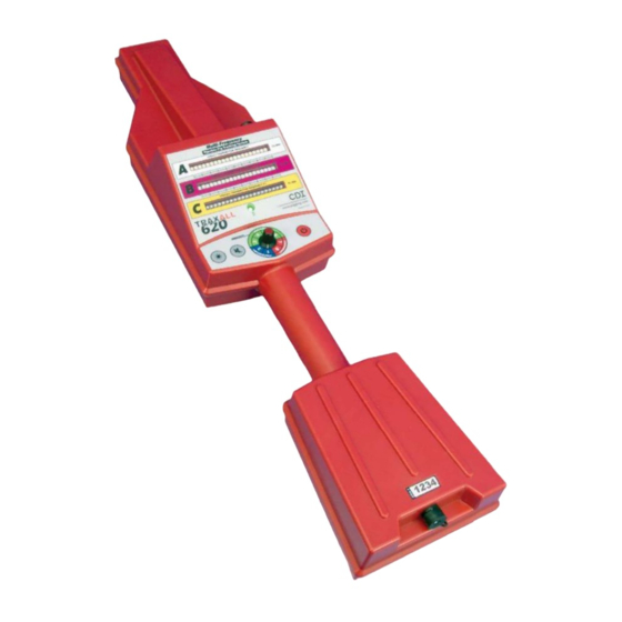
COMPONENTS OVERVIEW TRAXALL 620/501/500 USER GUIDE Components TRANSMITTER SENSOR ANTENNA REMOTE ANTENNA PORT CONTROLS INDICATORS HANDLE BATTERIES SERIAL NO. PASSAGE INDICATION OUTPUT PORT Page 8 of 32... - Page 9 Serial Number For reference when communica ng with CDI about your TRAXALL. Passage Indica on Output Port Devices such as the op onal external fl asher shown here or the LineStat event no fi...
-
Page 10: Controls And Indicators
COMPONENTS/CONTROLS OVERVIEW TRAXALL 620/501/500 USER GUIDE Controls and Indicators TRANSMITTER SIGNAL STRENGTH LED ARRAY: 22 Hz (“Legacy”) 27.3 Hz 31.3 Hz BATTERY STRENGTH INDICATOR POWER ON/OFF GAIN SELECTION BRIGHTNESS SPEAKER SWITCH MUTE Page 10 of 32... - Page 11 Rows B and C indicate signals from CDI’s exclusive X-Series programmable transmi ers. Row B is for a CDI 27.3 Hz transmi er frequency and Row C is for a CDI 31.3 Hz transmi er.
-
Page 12: Getting Started
UNPACKING/BATTERIES GETTING STARTED TRAXALL 620/501/500 USER GUIDE GETTING STARTED Unpacking The TRAXALL is shipped preassembled. It is only necessary to insert the ba eries (included). Install Ba eries Open the TRAXALL ba ery compartment with phillips screwdriver (included). (included). (included). Page 12 of 32... - Page 13 STARTUP GETTING STARTED TRAXALL 620/501/500 USER GUIDE Insert six AA-cell alkaline ba eries (also included). Observe ba ery polarity as shown on receptacle. Check seal for deforma on, cracks, tears, or foreign objects. Replace cover. gn objects. Replace cover. n objects. Replace cover. Tighten screws carefully and evenly to maintain carefully and evenly to maintain a weatherproof seal.
-
Page 14: Operation
OPERATION TRAXALL 620/501/500 USER GUIDE DETECTION OPERATION Your TRAXALL 620 can be used for loca ng (Pinpoin ng or Walking a pipeline) or in a Sta onary mode to confi rm a passage. Applica on: Passage Detec on Se ng: 7–8 Use your TRAXALL to detect passage of a moving pig, or to confi... - Page 15 DETECTION OPERATION TRAXALL 620/501/500 USER GUIDE Align the TRAXALL along and as close to pipeline as shown. The TRAXALL may be posi oned directly onto an exposed pipeline. (Note molded shape on case bo om to aid alignment.) Page 15 of 32...
- Page 16 DETECTION OPERATION TRAXALL 620/501/500 USER GUIDE The TRAXALL can be posi oned at a Pig Trap to confi rm arrival or behind a valve to confi rm clearance. Page 16 of 32...
- Page 17 DETECTION OPERATION TRAXALL 620/501/500 USER GUIDE Once a passage has been detected, the LED array will light up. Here, the TRAXALL 620 indicates a pig confi gured with a 27.3 Hz transmi er has arrived. Page 17 of 32...
-
Page 18: Leapfrogging
LOCATING OPERATION TRAXALL 620/501/500 USER GUIDE Applica on: “Leapfrogging” Se ng: 7–8 Leapfrogging is a common method of determining the vicinity of a pipeline pig. This is done by se ng up the TRAXALL at a point along a pipeline, no ng a passage, and then moving the system – or deploying addi onal TRAXALL units –... -
Page 19: Loca Ng
LOCATING OPERATION TRAXALL 620/501/500 USER GUIDE Applica on: Loca ng Se ng: 3–6 Once you have a general idea where along a pipeline a pig may be located, set the Gain Selec on Switch to “Walking” (3–6) and traverse along the pipeline star ng from the pig’s last known posi on. Keep the TRAXALL parallel to the pipeline while monitoring the LED display. - Page 20 OPERATION TRAXALL 620/501/500 USER GUIDE LOCATING Here, the operator is approaching three pigs in close proximity to each other and confi gured with ac ve transmi ers. LED arrays are independent of each other and each will light up according to rela ve signal strength as approached.
- Page 21 LOCATING OPERATION TRAXALL 620/501/500 USER GUIDE Whether detec ng a passage, tracking, or loca ng, you are looking for the maximum (peak) wave of a transmi er signal. This is a 3-D representa on of a how TRAXALL “sees” an electromagne c fi...
- Page 22 PINPOINTING OPERATION TRAXALL 620/501/500 USER GUIDE Applica on: Pinpoin ng Se ng: 1–2 Once a pig has been found, use the pinpoin ng feature for a precise loca on. Set the Gain Selec on Switch to “Pinpoin ng” (1–2) and hold TRAXALL perpendicular to the pipeline.
-
Page 23: Pinpoin Ng
PINPOINTING OPERATION TRAXALL 620/501/500 USER GUIDE Pinpoin ng diff ers from tracking/loca ng in that you are looking for the minimum (null) of a transmi er signal rather than a peak. This is a 3-D representa on of a how TRAXALL “sees” an electromagne c fi... - Page 24 PINPOINTING OPERATION TRAXALL 620/501/500 USER GUIDE As you move the antenna closer to the pig, the signal strength increases un l you reach the peak, then drops to li le or no signal as you approach the signal null point. APPROACHING PEAK PEAK APPROACHING NULL...
- Page 25 PINPOINTING OPERATION TRAXALL 620/501/500 USER GUIDE At the null point you are directly over the pig. Move the antenna back an inch or two, and the signal strength will rise (depending on gain se ng). Move farther away and the signal will disappear altogether. RECEDING SIGNAL PEAK NULL...
-
Page 26: Optional Equipment
REMOTE FLASHER OPTIONAL EQUIPMENT TRAXALL 620/501/500 USER GUIDE Remote Flasher The Remote Flasher is useful for at-a- or at t-a- glance passage confi rma on where an wher unmanned passage must be monitored. monit tored. When the 15 [4.5 m] cable is a ached, the fl... -
Page 27: Remote Antenna
REMOTE ANTENNA OPTIONAL EQUIPMENT TRAXALL 620/501/500 USER GUIDE Remote Antenna The water- ght Remote Antenna is ideal for tracking and loca ng over a submerged or limited-access pipeline. You can also monitor a passage from the shelter of a vehicle during inclement clement weather. -
Page 28: Cdi X-Series Transmi Ers
OPTIONAL EQUIPMENT TRAXALL 620/501/500 USER GUIDE CDI X-Series Transmi ers CDI X-100, X-200, X-300, and X-400 TRAXALL-compa ble Transmi ers off er both programmable frequency and power control through CDI’s proprietary FieldLink wireless communica ons system. Frequency Control allows the operator to confi gure the transmi er to one of TRAXALL’s colorized frequencies, or the 22 Hz legacy frequency... -
Page 29: Traxall Linestat
LINESTAT OPTIONAL EQUIPMENT TRAXALL 620/501/500 USER GUIDE TRAXALL LineStat CDI’s LineStat radio system provides your TRAXALL 620 or 501 with the ability to autonomously monitor pig passages and send remote no fi ca ons as emails or text messages. SAMPLE... -
Page 30: Warranty
Upon receipt of the equipment and Purchase Order, CDI will examine the equipment and make a determina on of the nature and cause of the defect. If the defect is not covered by the warranty, CDI will quote to Purchaser the cost for replacement or repair equipment, and will not proceed un l Purchaser delivers a wri en acceptance of the quota on. -
Page 31: Care, Maintenance, & Servicing
Failure to perform these opera ons nullifi es this warranty. CDI equipment should only be operated by qualifi ed personnel who are familiar with any and all manuals and procedures for said equipment’s opera on. -
Page 32: About Cdi
Oklahoma, just 12 miles from downtown Tulsa. Incorporated in 1982, CDI has proudly been manufacturing products in the United States for more than 32 years. CDI currently employs 45 people in the areas of electronics and mechanical design, so ware and fi rmware programming, electronics manufacture, machining, and more.
Need help?
Do you have a question about the TRAXALL 620: TRAXALL 501: TRAXALL 500: and is the answer not in the manual?
Questions and answers