
Subscribe to Our Youtube Channel
Related Manuals for TRI tool PIPEMASTER PFM614


Summary of Contents for TRI tool PIPEMASTER PFM614
-
Page 1: Table Of Contents
TABLE OF CONTENTS CUSTOMER MESSAGE Inside Front Cover SAFETY PRECAUTIONS GENERAL DESCRIPTION SPECIFICATIONS HYDRAULIC SCHEMATIC OPERATION CUTTING SPEEDS AND FEEDS TOOLING CLAMPING PADS MAINTENANCE TROUBLE SHOOTING ACCESSORIES ILLUSTRATED PARTS BREAKDOWN TOOL BIT RESHARPENING POLICY Inside Back Cover WARRANTY INFORMATION Inside Back Cover... - Page 2 Copyright 2011 Proprietary property of TRI TOOL Inc. No reproduction, use, or duplication of the information shown hereon is permitted without the express written consent of TRI TOOL Inc.
-
Page 3: Safety Precautions
® Model PFM 614 PIPEMASTER SAFETY PRECAUTIONS IN GENERAL When using rotating head cutting equipment, basic safety precautions should always be followed to reduce the risk of personal injury. Operate this tool only in accordance with specific operating instructions. Do not override the deadman switch on the power unit. Locking down, ob- WARNING: structing, or in any way defeating the deadman switch on the power drive unit may result in serious injury. - Page 4 TRI TOOL INC. TOOL CARE Maintain tools with care. Keep tools in good operating condition. Sharp tool bits perform better and safer than dull tool bits. Well maintained tools function properly when needed. Check for damaged parts. If a tool has malfunctioned, been dropped or hit, it must be checked for damage.
- Page 5 ® Model PFM 614 PIPEMASTER Remove adjusting keys and wrenches before applying power to the equipment. De- velop a habit of checking the tool before turning it on to make sure that all keys and wrenches have been removed. Do not force tools. Tools and tool bits function better and safer when used at the feed and speed rate for which they were designed.
-
Page 6: General Description
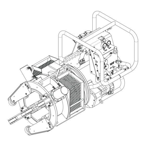
TRI TOOL INC. GENERAL DESCRIPTION The Model PFM 614 is a portable OD mount machine tool for beveling and facing 6” through 14” pipe. The tool is configured with a dual hydraulic drive motor powering a set of helical gears attached to the main spindle. An auto-feed hydraulic cylinder with rapid and slow feed control provides accurate cutting head control. -
Page 7: Specifications
® Model PFM 614 PIPEMASTER SPECIFICATIONS DESIGN AND OPERATING FEATURES The tool accepts it’s own torque through the OD clamping head. The OD clamping head provides, fast and accurate clamps of the pipe. All wrenches needed for operation are provided with the system. The lathe is provided with lifting frame. - Page 8 TRI TOOL INC. Envelope Drawing 26.84" (681.7 mm) 33.97" (862.8 mm) 45.35" (1151.9 mm) 36.81" (940.0 mm) 57.33" (1456.3 mm) 80.27" (2038.8 mm) SPECIFICATIONS Weight 2,650 lbs. (1,202 Kg) Clearances and Dimensions Maximum Rotating Head DIA 17.375” (441.3 mm) Length, Approximate (parallel to axis of pipe) 80.27”...
- Page 9 Tubing or pipe with greater wall thickness may be handled provided the ID is equal to or greater than 4.89” (124.2 mm) and the OD is equal to or less than 14.00” (355.6 mm). Contact TRI TOOL INC. for heavier wall procedures.
- Page 10 Hydraulically actuated cylinders expand the clamping pads. Drive System Dual Hydraulic Drive Requires a separate hydraulic power supply. Reference the TRI TOOL HPU 75-60/5. Power Requirements 60 GPM at 2000 psi 5 GPM at 2000 psi 92-1535 : Orig. 110210...
-
Page 11: Hydraulic Schematic
CYLINDER CAGE SAFETY VALVE PCV7 CLAMP PRESSURE PCV1 PCV2 PCV3 PCV4 PCV5 PCV6 PSV1 TRI TOOL INC HPU 70-60/5 (75 HP Motor w/ Tandem Pumps) DRIVE 60 GPM PUMP PRESSURE CLAMP FEED RAPID DRIVE FEED 5 GPM PUMP TRI TOOL INC... - Page 12 TRI TOOL INC. SETUP AND OPERATION TOOL MODULE HEIGHT ADJUSTMENT Tool Holder Retaining Socket Set Screw Tool Module Tool Module Retaining Cap Screw Tracking Wheel Assembly ID Brush Tool Spacer/Shim Tool Holder Retaining Tool Holder Hex Head Screw Tool Module Recommended Set Height is .10" to .25"...
- Page 13 ® Model PFM 614 PIPEMASTER TOOL MODULE HEIGHT ADJUSTMENT Loosen the tool module retaining cap screw. Confirm the eccentric wheel adjustment is in the middle of its travel. Slide the tool module to recommended set height. Set all other tool modules at the same height and tighten all retaining screws. Mounting Wheel Assembly...
- Page 14 TRI TOOL INC. Tool Holder Set Up - Step 'A' Spacer TOOL HOLDER ASSEMBLY SET UP - STEP 'A' Before any adjustment can be made all hex screws and the I.D. brush bracket must be loosened. Set axial set screw in the tool holder protruding 1/8" from the back of the tool holder.
- Page 15 ® Model PFM 614 PIPEMASTER Tool Holder Set Up - Step 'B' Spacer TOOL HOLDER ASSEMBLY SET UP - STEP 'B' Before any adjustment can be made all hex screws and the I.D. brush bracket must be loosened. Use the axial set screw in the back of the tool holder to adjust the axial height to the measurement taken in step ‘A’.
- Page 16 TRI TOOL INC. Tool Holder Set Up - Step 'C' Spacer TOOL HOLDER ASSEMBLY SET UP - STEP 'C' Before any adjustment can be made all hex screws and the I.D. brush bracket must be loosened. Use the axial set screw in the back of the tool holder to adjust the axial height to the measurement taken in step ‘B’.
- Page 17 ® Model PFM 614 PIPEMASTER Tool Holder Set Up - Step 'D' Spacer TOOL HOLDER ASSEMBLY SET UP - STEP 'D' Before any adjustment can be made all hex screws and the I.D. brush bracket must be loosened. To determine the axial height of the tool holder use the dimension taken in step ‘A’...
- Page 18 TRI TOOL INC. OPERATING INSTRUCTIONS Measure the OD of the pipe to be machined. Select the right set of clamp pads to clamp the pipe. Reference the 'Clamping Pads' section. Install the clamp pads to the ID of the machine.
- Page 19 ® Model PFM 614 PIPEMASTER Remember this number and multiply it by the feed rate. Formula: Feed rate per revolution x rotation per minute = linear travel per minute. Example: 0.006” per revolution x 152 RPM = 0.912” of linear travel of the head. Set the feed rate of the PFM by using a magnetic base dial indicator attached to the frame of the PFM.
- Page 20 TRI TOOL INC. Advance the head by jogging gently the fast feed forward lever, until the Tool Holders tracking wheels are engaged in the pipe. Beware not to bump the end of the pipe with the inserts. Turn on power to the head by shifting the drive lever to ‘On’.
-
Page 21: Cutting Speeds And Feeds
® Model PFM 614 PIPEMASTER CUTTING SPEEDS AND FEEDS 6" Pipe @ 152 RPM Head Speed & 264 SFM 8" Pipe @ 152 RPM Head Speed & 264 SFM Wall Thickness Feed Rate Feed Wall Thickness Feed Rate Feed (Inch) (In/Rev.) (In./Min.) (Inch) - Page 22 TRI TOOL INC. TOOLING Parts List, Tool Holders, Standard Selection Item Part Description 49-0605 TOOL HOLDER, 0 DEG. FACE/RADIUS, RH 49-0603 TOOL HOLDER, 1 DEG. BEVEL, RH 49-0613 TOOL HOLDER, 7 DEG. BEVEL, RH 49-0604 TOOL HOLDER, 30 DEG. BEVEL, RH 49-0608 TOOL HOLDER, 2 DEG.
- Page 23 ® Model PFM 614 PIPEMASTER Parts List, Inserts/Hardware Item Part Description 30-3100 INSERT TRIANGULAR .047 RADIUS 30-3101 INSERT TRIANGULAR .094 RADIUS 30-3102 INSERT TRIANGULAR .125 RADIUS 30-3103 SHIM SEATS, .031/.063 RADIUS 30-3104 SHIM SEATS, .094/.125 RADIUS 30-3105 LOCK PIN, INSERT 33-1261 SCREW, SET, 3/8-16 X 3/4", HDOG Parts List, Spacer Kit, Tool Holder (P/N 05-0406)
- Page 24 TRI TOOL INC. TOOL HOLDER AND CHIP BREAKER SET UP 0°/Facing Tool Holder 33-1261 Adjustment Screw 49-0605 30-3105 30-3103 0° to 15° Tool Holder 33-1261 Adjustment Screw 49-0603 30-3105 30-3103 20° to 30° Tool Holder 33-1261 Adjustment Screw 49-0606 30-3105 30-3103 92-1535 : Orig.
-
Page 25: Clamping Pads
® Model PFM 614 PIPEMASTER CLAMPING PADS Fixed Fixed Adapter Adapter Adjustable Block Block Mounting (Steel) Mounting (Aluminum) Mounting Range Screw Screw 6" Pipe 48-1752 44-1084 33-0106 48-2606 8" Pipe 48-1752 33-0107 44-1083 33-0106 48-2606 10" Pipe 48-1752 33-0107 44-1082 33-0106 48-1662 12"... -
Page 26: Maintenance
TRI TOOL INC. MAINTENANCE Hours Maintenance Note Item Maintenance Activity Picture Operation Item No. Clean all debris from tool Spray all bare metal with light oil check oil level add as requred 1500 Drain oil and refill main housing NOTES: Oil level should be in center of oil sight when tool has been left off for 10 minutes. - Page 27 ® Model PFM 614 PIPEMASTER Item #2 Fill Here Vent Fitting (7.5 - 15 PSI) Drain Plug Oil Sight 92-1535 : Orig. 110210...
-
Page 28: Trouble Shooting
TRI TOOL INC. TROUBLE SHOOTING Problem: The Tool Bit Chatters The tool bit is loose or overextended. The tool bit is damaged. The tool holder is too loose in the slides. The cutting speed is too fast. The clamping pads are loose on the pipe or tube. - Page 29 ® Model PFM 614 PIPEMASTER Problem: There is a loss of air power The air supply pressure is too low. The air filter is plugged. The air line size is insufficient. The air line is too long. Problem: There is a loss of hydraulic power The hydraulic supply pressure is too low.
-
Page 30: Accessories
TRI TOOL INC. ACCESSORIES The following accessories are recommended for use with the Model PFM 614 and are available from TRI TOOL INC. Item Part Description 01-1829 HYD. POWER UNIT 75-60/5, 380/480 05-0387 HOSE KIT 55-0345 HOSE ASSEMBLY, QD, 3/4" ID X 50 FT 55-0249 HOSE ASSEMBLY, QD, DRIPLESS, 1 1/4"... -
Page 31: Illustrated Parts Breakdown
® Model PFM 614 PIPEMASTER ILLUSTRATED PARTS BREAKDOWN MODEL PFM 614 (P/N 01-1941) Components 33 34 35 36 37 92-1535 : Orig. 110210... - Page 32 TRI TOOL INC. MODEL PFM 614 (P/N 01-1941) Hose Locations (Top View) Parts List, PFM 614 (P/N 01-1941) Item Part Description 02-2524 MODEL PFM614 SUB-ASSY 07-0063 HYD.ASSY,CONTROL PANEL,PFM614 08-0686 BLOCK ASSY,TOOL,PFM 614/612 19-1018 HOUSING ASSY,GEAR BOX 19-1270 HOUSING ASSY,CLAMP END,PFM614...
- Page 33 ® Model PFM 614 PIPEMASTER MODEL PFM 614 (P/N 01-1941) Hose Locations (L-Manifold) Parts List, PFM 614 (P/N 01-1941) Continued Item Part Description 33-0045 SCREW,CAP,1/4-20 X 1-3/4 33-0055 SCREW,CAP,5/16-18 X 7/8 33-0067 SCREW,CAP,3/8-16 X 1/2 33-0071 SCREW,CAP,3/8-16 X 1 33-0106 SCREW,CAP,1/2-13 X 1-1/4 33-0107 SCREW,CAP,1/2-13 X 1-1/2...
- Page 34 TRI TOOL INC. MODEL PFM 614 (P/N 01-1941) Hose Locations (Manifold Control Assembly) Parts List, PFM 614 (P/N 01-1941) Continued Item Part Description 33-1407 SCREW,SHLDR,1/2 X 1-1/2 33-2444 SCREW,CAP,LOW HD,1/2-13 X 1" 33-2445 SCREW,CAP,MOD 34-0027 WASHER,FLAT,SAE,5/16 X 3/4X1/8 34-0162 WASHER,THRST,1/2X 15/16 X 1/32...
- Page 35 ® Model PFM 614 PIPEMASTER Parts List, PFM 614 (P/N 01-1941) Continued Item Part Description 44-1081 SPACER ASSY,FIXED PAD,12" 44-1082 SPACER ASSY,FIXED PAD, 10" 44-1083 SPACER ASSY.FIXED PAD,8" 44-1084 SPACER ASSY.FIXED PAD,6" 47-1559 BRACKET,HINGE,LEFT,CHIPGUARD 47-1590 BRACKET,HINGE,RIGHT,CHIPGUARD 47-1594 BRACKET,CLAMPING 48-1662 BLOCK,CLAMP,ADJUSTABLE,8"-12"P 48-1752 CLAMPING PAD ASSY,FIXED,12"...
- Page 36 TRI TOOL INC. Parts List, PFM 614 (P/N 01-1941) Continued Item Part Description 55-0793 HOSE ASSY 50"0-90-4 55-0825 HOSE ASSY 24" 0-90-4 55-0789 HOSE ASSY 38" 0-90-4 55-0789 HOSE ASSY 38" 0-90-4 55-0794 HOSE ASSY 18" 0-0-4 55-0795 HOSE ASSY 30" 0-0-4...
- Page 37 ® Model PFM 614 PIPEMASTER PFM 614 SUB-ASSEMBLY (P/N 02-2524) Parts List, PFM 614 Sub-Assembly (P/N 02-2524) Item Part Description 19-1034 WELDMENT, MAIN HOUSING 19-1013 HOUSING, BEARING, FEED 20-0924 SHAFT, FEED 20-1104 SHAFT, SPINDLE 24-3009 PLATE, LOCK, TOOL HOLDER 27-0825 ADAPTER, COLLAR, FEED 28-0314 O-RING, 11.975 ID X .210 W...
- Page 38 TRI TOOL INC. PFM 614 SUB-ASSEMBLY (P/N 02-2524) Parts List, PFM 614 Sub-Assembly (P/N 02-2524) Continued Item Part Description 31-0220 KEY,DRIVE 33-0040 SCREW,CAP,1/4-20 X 3/4 33-0053 SCREW,CAP,5/16-18 X 5/8 33-0072 SCREW,CAP,3/8-16 X 1 1/4 33-0075 SCREW,CAP,3/8-16 X 2 33-0076 SCREW,CAP,3/8-16 X 2 1/4...
- Page 39 ® Model PFM 614 PIPEMASTER Parts List, PFM 614 Sub-Assembly (P/N 02-2524) Continued Item Part Description 75-0174 COUPLING,ROD.,MOD. 75-0148 CYLINDER, FEED 28-0057 SEAL,FELT,1/8 X 3/16" X BULK 30.96" 54-0531 FITTING,1/2 EPIPE - 1/8 IPIPE 54-0606 FITTING,PRESSURE RELIEF,1/8PTF,71/2-15PSI 30-3080 OIL SIGHT GLASS,M20 X 1.5 54-0489 PLUG,PRESSURE,1/2"...
- Page 40 TRI TOOL INC. HYDRAULIC ASSEMBLY, CONTROL PANEL (P/N 07-0063) 92-1535 : Orig. 110210...
- Page 41 ® Model PFM 614 PIPEMASTER Parts List, Hydraulic Assembly, Control Panel (P/N 07-0063) Item Part Description 07-0064 HYD.ASSY,L-MANIFOLD,PFM614 24-3297 PLATE,CONTROL,HYD,MANIFOLD 24-3303 PLATE,MANIFOLD MOUNT,RIGHT 24-3304 PLATE,MANIFOLD MOUNT,LEFT 33-0071 SCREW,CAP,3/8-16 X 1 33-0108 SCREW,CAP,1/2-13 X 1-3/4 33-0082 SCREW,CAP,3/8-16 X 4 34-0018 WASHER,FLAT,SAE,3/8"NOMINAL 35-0095 NUT,LK,3/8-16 X 7/16 53-0244...
- Page 42 TRI TOOL INC. TOOL MODULE ASSEMBLY [1 OF 2] (P/N 08-0686) FRONT VIEW Parts List, Tool Module Assembly (P/N 08-0686) Item Part Description 20-0961 SHAFT,PIVOT,TOOL HOLDER 24-2144 PLATE,NUT,TOOL HOLDER 24-2147 PLATE,WEAR,TOOL HOLDER 24-2202 PLATE,BASE,TOOL HOLDER 28-0360 FELT,RING,2.000 OD X 1.720 ID X .125 W...
- Page 43 ® Model PFM 614 PIPEMASTER TOOL MODULE ASSEMBLY [2 OF 2] (P/N 08-0686) BACK VIEW Parts List, Tool Module Assembly (P/N 08-0686) Continued Item Part Description 30-2837 HOLDER, BRUSH CHANNEL 30-3226 BRUSH, S STEEL, STRIP 32-0657 PIN,ROLLER,TOOL HOLDER 33-0116 SCREW,CAP,1/2-13 X 4 33-0284 SCREW,BUTTON,1/4-20 X 3/8 33-0347...
- Page 44 TRI TOOL INC. Parts List, Tool Module Assembly (P/N 08-0686) Continued Item Part Description 35-0662 NUT,PIVOT,TOOL HOLDER 35-0663 NUT,LOCK,PIVOT,TOOL HOLDER 40-0306 SPRING,DIE,1-1/4"OD X 1-1/2"LG,BRONZE 47-1588 BRACKET,BRUSH,TOOL HOLDER 48-1660 BLOCK,SPRING,TOOL HOLDER 48-1712 BLOCK,TOOL HOLDER 54-0304 PLUG,PRESSURE,FLUSH SKT 3/8NPT 61-0168 ROLLER,PRESSURE 61-0170...
- Page 45 ® Model PFM 614 PIPEMASTER GEAR BOX HOUSING ASSEMBLY (P/N 19-1018) Parts List, Gear Box Housing Assembly (P/N 19-1018) Item Part Description 19-1012 HOUSING,DRIVE 28-0319 O-RING,5.234"ID, .139" W 32-0140 PIN,DOWEL,1/4 DIA X 3/4 33-0058 SCREW,CAP,5/16-18 X 1 1/2 33-0073 SCREW,CAP,3/8-16 X 1 1/2 33-0109 SCREW,CAP,1/2-13 X 2 33-0120...
- Page 46 TRI TOOL INC. HOUSING ASSEMBLY, CLAMP END (P/N 19-1270) Parts List, Housing Assembly, Clamp End (P/N 19-1270) Item Part Description 29-0455 BEARING, SLEEVE, 1 1/4" ID X 1 1/2" OD X 3" LG 29-0454 BEARING, SLEEVE, 2 1/2" ID X 3" OD X 3" LG 33-0108 SCREW, CAP, 1/2-13 X 1 3/4"...
- Page 47 ® Model PFM 614 PIPEMASTER HYDRAULIC ASSEMBLY, L-MANIFOLD (P/N 07-0064) 92-1535 : Orig. 110210...
- Page 48 TRI TOOL INC. Parts List, Hydraulic Assembly, L-Manifold (P/N 07-0064) Item Part Description 53-0108 VALVE,BALL,HIGH PRESSURE,16SAE 53-0109 VALVE,BALL,HI-PRESSURE,1-1/4" 53-0122 MANIFOLD, MAIN 53-0196 VALVE BODY, DIR CONTROL 53-0197 VALVE,CARTRIDGE,DIR CONTROL 54-0233 ADAPTER,1"O-RING TO 1"NPTM 54-0333 COUPLER,QD,HYD,DRIPLESS,FEMALE 54-0335 DUST PLUG,DRIPLESS 54-0459 COUPLING,QD,HYD.MALE W/FLANGE...
- Page 49 ® Model PFM 614 PIPEMASTER MANIFOLD CONTROL ASSEMBLY (P/N 53-0244) Parts List, Manifold Control Assembly (P/N 53-0244) Item Part Description 33-0507 SCREW,SET,1/4-20 X 1 CUP PT 33-0512 SCREW,SET,5/16-18 X 1/4 CUP PT 35-0203 NUT,LK,1/4-20 41-0214 HANDLE,THREADED,5/16-18 X 3/8 42-0066 KNOB,KNURLED 53-0203 MANIFOLD ASSY,PFM 54-0515...
- Page 50 TRI TOOL INC. MANIFOLD ASSEMBLY (P/N 53-0203) 92-1535 : Orig. 110210...
- Page 51 ® Model PFM 614 PIPEMASTER Parts List, Manifold Assembly (P/N 53-0203) Item Part Description 30-4211 BLOCK, CONTROL MANIFOLD 53-0107 VALVE, FLOW CONTROL 53-0126 VALVE, JOG SWITCH 53-0205 VALVE, MANUAL ROTARY 53-0207 VALVE, MANUAL ROTARY 53-0208 VALVE, PRESSURE SEQUENCE 53-0209 VALVE, PILOT OPERATED CHECK 53-0210 VALVE, CHECK 53-0211...
- Page 52 TRI TOOL INC. GUIDE WHEEL ASSEMBLY (P/N 61-0179) Parts List, Guide Wheel Assembly (P/N 61-0179) Item Part Description 33-1289 SCREW, SHLDR, 1/2" D X 2" 47-1592 WELDMENT,BRACKET,GUIDE WHEEL 61-0180 WHEEL 92-1535 : Orig. 110210...
- Page 53 ® Model PFM 614 PIPEMASTER WHEEL ASSEMBLY, TRACKING (P/N 61-01XX) Parts List, Wheel Assembly, Tracking, Small (P/N 61-0186) Item Part Description 29-0080 BRG, BALL, 3/4" X 1 3/16" X 9/32" 61-0166 WHEEL, TRACKING, SMALL Parts List, Wheel Assembly, Tracking, Medium (P/N 61-0170) Item Part Description...
Need help?
Do you have a question about the PIPEMASTER PFM614 and is the answer not in the manual?
Questions and answers