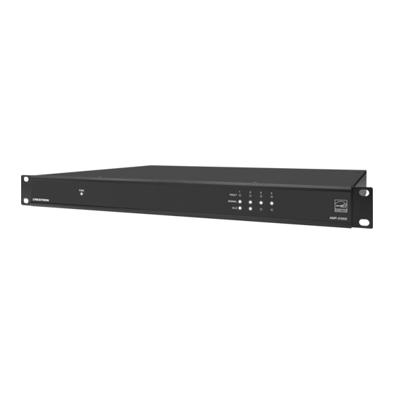
Crestron X Series Product Manual

Crestron X Series Product Manual

Hide thumbs Also See for X Series:

Advertisement

Quick Links

AMP-X500, AMP-X750, and AMP-X1000
X-Series Amplifiers
Product Manual
Crestron Electronics, Inc.

Advertisement

Table of Contents
loading
Need help?

Need help?

Do you have a question about the X Series and is the answer not in the manual?

Questions and answers

Summary of Contents for Crestron X Series

  • Page 1 AMP-X500, AMP-X750, and AMP-X1000 X-Series Amplifiers Product Manual Crestron Electronics, Inc.
  • Page 2 Certain Crestron products contain open source software. For specific information, please visit www.crestron.com/opensource. Crestron and the Crestron logo are either trademarks or registered trademarks of Crestron Electronics, Inc. in the United States and/or other countries. Other trademarks, registered trademarks, and trade names may be used in this document to refer to either the entities claiming the marks and names or their products.
  • Page 3: Table Of Contents

    Contents Overview Products AMP-X500 AMP-X750 AMP-X1000 Specifications AMP-X500 Specifications Dimension Drawings AMP-X750 Specifications Dimension Drawings AMP-X1000 Specifications Dimension Drawings Installation AMP-X500 Installation In the Box Install the Device Connect the Device Observe the LED Indicators AMP-X750 Installation In the Box Install the Device Connect the Device Observe the LED Indicators...
  • Page 4 iv • Contents Product Manual — Doc. 9328A...
  • Page 5: Overview

    Overview X-Series amplifiers are high performance, compact, energy efficient, professional grade amplifiers. Supporting Lo-Z and Hi-Z operation, these multichannel amplifiers are suitable for both residential and commercial configurations. Products The following products are described in this product manual. AMP-X500 on page 6 AMP-X750 on page 8 AMP-X1000 on page 10 Product Manual —...
  • Page 6: Amp-X500

    AMP-X500 ENERGY STAR® certified power amplifier Compact 1 RU form factor with cool-running operation Quiet, fanless convection-cooled design Configurable for either Lo-Z (4/8 Ω) or Hi-Z (70V or 100V) operation BUS line input and output for sending the same signal to multiple amps Low noise, low distortion, high headroom Comprehensive fault and speaker protection Captive speaker connectors for secure and robust connectivity...
  • Page 7 The amplifier is high-density stackable with other Crestron amps, allowing multiple units to be installed vertically in an equipment rack without needing extra ventilation space. Rack mount parts are included, so no additional mounting accessories or rack shelves are required.
  • Page 8: Amp-X750

    AMP-X750 ENERGY STAR® certified power amplifier Compact 1 RU form factor with cool-running operation Quiet, fanless convection-cooled design Configurable for either Lo-Z (4/8 Ω) or Hi-Z (70V or 100V) operation BUS line input and output for sending the same signal to multiple amps Low noise, low distortion, high headroom Comprehensive fault and speaker protection Captive speaker connectors for secure and robust connectivity...
  • Page 9 The amplifier is high-density stackable with other Crestron amps, allowing multiple units to be installed vertically in an equipment rack without needing extra ventilation space. Rack mount parts are included, so no additional mounting accessories or rack shelves are required.
  • Page 10: Amp-X1000

    AMP-X1000 ENERGY STAR® certified power amplifier Compact 1 RU form factor with cool-running operation Configurable for either Lo-Z (4/8 Ω) or Hi-Z (70V or 100V) operation BUS line input and output for sending the same signal to multiple amps Low noise, low distortion, high headroom Comprehensive fault and speaker protection Captive speaker connectors for secure and robust connectivity Balanced and unbalanced inputs...
  • Page 11 The amplifier is high-density stackable with other Crestron amps, allowing multiple units to be installed vertically in an equipment rack without needing extra ventilation space. Rack mount parts are included, so no additional mounting accessories or rack shelves are required.
  • Page 12: Specifications

    Specifications Refer to the following sections for more information on the specifications for various X-Series amplifiers. AMP-X500 Specifications on page 13 AMP-X750 Specifications on page 17 AMP-X1000 Specifications on page 21 Product Manual — Doc. 9328A AMP-X500, AMP-X750, and AMP-X1000 • 12...
  • Page 13: Amp-X500 Specifications

    AMP-X500 Specifications Product specifications for the AMP-X500 are provided below. Audio Input Signal Types Balanced or unbalanced analog line-level Output Power Total output power from all channels combined (simultaneously) is up to 500 W; Output power per channel is 250 W (4 or 8 Ω), 500 W (8 Ω Bridged), 250 W (70V/100V) Frequency Response 20 Hz to 20 kHz ±0.5 dB at 1 W...
  • Page 14 BUS OUTPUT (2) paired RCA connectors, female; Unbalanced line-level audio outputs REMOTE (1) 2-pin 3.5 mm detachable terminal block; Connect to dry contact closure to place amplifier in standby mode (1) 6-32 screw; Chassis ground lug 100-240V~ 1.2-0.6A (1) IEC 60320 C14 main power inlet; 50/60 Hz Mates with removable power cord, included Controls & Indicators...
  • Page 15 Front Panel Metal, black finish with polycarbonate label overlay Mounting Freestanding or 1 RU 19 in. rack mountable; Stackable with other Crestron AMP series products (adhesive feet and rack mounting hardware all included) Dimensions Height 1.75 in (44 mm) without feet;...
  • Page 16: Dimension Drawings

    Dimension Drawings 16 • AMP-X500, AMP-X750, and AMP-X1000 Product Manual — Doc. 9328A...
  • Page 17: Amp-X750 Specifications

    AMP-X750 Specifications Product specifications for the AMP-X750 are provided below. Audio Input Signal Types Balanced or unbalanced analog line-level Output Power Total output power from all channels combined (simultaneously) is up to 750 W; Output power per channel is 250 W (4 or 8 Ω), 500 W (8 Ω Bridged), 250 W (70V/100V) Frequency Response 20 Hz to 20 kHz ±0.5 dB at 1 W...
  • Page 18 BUS OUTPUT (2) paired RCA connectors, female; Unbalanced line-level audio outputs REMOTE (1) 2-pin 3.5 mm detachable terminal block; Connect to dry contact closure to place amplifier in standby mode (1) 6-32 screw; Chassis ground lug 100-240V~ 1.2-0.6A (1) IEC 60320 C14 main power inlet; 50/60 Hz Mates with removable power cord, included Controls & Indicators...
  • Page 19 Front Panel Metal, black finish with polycarbonate label overlay Mounting Freestanding or 1 RU 19 in. rack mountable; Stackable with other Crestron AMP series products (adhesive feet and rack mounting hardware all included) Dimensions Height 1.75 in (44 mm) without feet;...
  • Page 20: Dimension Drawings

    Dimension Drawings 20 • AMP-X500, AMP-X750, and AMP-X1000 Product Manual — Doc. 9328A...
  • Page 21: Amp-X1000 Specifications

    AMP-X1000 Specifications Product specifications for the AMP-X1000 are provided below. Audio Input Signal Types Balanced or unbalanced analog line-level Output Power Total output power from all channels combined (simultaneously) is up to 1000 W; Output power per channel is 250 W (4 or 8 Ω), 500 W (8 Ω Bridged), 250 W (70V/100V) Frequency Response 20 Hz to 20 kHz ±0.5 dB at 1 W...
  • Page 22 BUS INPUT (2) paired RCA connectors, female; Unbalanced line-level audio inputs BUS OUTPUT (2) paired RCA connectors, female; Unbalanced line-level audio outputs REMOTE (1) 2-pin 3.5 mm detachable terminal block; Connect to dry contact closure to place amplifier in standby mode (1) 6-32 screw; Chassis ground lug 100-240V~ 1.2-0.6A (1) IEC 60320 C14 main power inlet;...
  • Page 23 Front Panel Metal, black finish with polycarbonate label overlay Mounting Freestanding or 1 RU 19 in. rack mountable; Stackable with other Crestron AMP series products (adhesive feet and rack mounting hardware all included) Dimensions Height 1.75 in (44 mm) without feet;...
  • Page 24: Dimension Drawings

    Dimension Drawings 24 • AMP-X500, AMP-X750, and AMP-X1000 Product Manual — Doc. 9328A...
  • Page 25: Installation

    Installation Refer to the following sections for instructions on how to install the various X-Series amplifiers. AMP-X500 Installation on page 26 AMP-X750 Installation on page 32 AMP-X1000 Installation on page 38 Product Manual — Doc. 9328A AMP-X500, AMP-X750, and AMP-X1000 • 25...
  • Page 26: Amp-X500 Installation

    AMP-X500 Installation Refer to the following sections to install the AMP-X500. In the Box on page 27 Install the Device on page 28 Connect the Device on page 29 Observe the LED Indicators on page 31 Product Manual — Doc. 9328A AMP-X500, AMP-X750, and AMP-X1000 •...
  • Page 27: In The Box

    In the Box Qty. Description AMP-X500 Additional Items Power cord (2061092) Connectors, speaker (2061091) Connectors, input, output, (2055207) Connector, 2-pin (2003574) Adhesive foot, black (2002390) 27 • AMP-X500, AMP-X750, and AMP-X1000 Product Manual — Doc. 9328A...
  • Page 28: Install The Device

    Install the Device The AMP-X500 can be placed on a flat surface or installed in a rack. Place on a Flat Surface Place the AMP-X500 on a table or other flat surface. Attach the four adhesive feet to the underside of the device. Mount on a Rack This device occupies 1U of rack space.
  • Page 29: Connect The Device

    Connect the Device Make the necessary connections as shown in the following illustration. CAUTIONS: Keep the device unplugged until all of the input and speaker wiring is complete. Check the speaker wires for shorts and frayed wiring around the speaker output connectors.
  • Page 30 Balanced/Unbalanced Audio Input Refer to the following table and illustration for analog audio input pin assignments and connection information. Signal Name Balanced Audio Input Unbalanced Audio Input L− Open Shield/ground Open Open Product Manual — Doc. 9328A AMP-X500, AMP-X750, and AMP-X1000 • 30...
  • Page 31: Observe The Led Indicators

    Observe the LED Indicators The LEDs provide the following information: LED Indicator Color Meaning Amber Power is being applied to the device. The device is booting. White Device is powered on with audio passing. Device is in standby mode. SIGNAL 1-2 White Signal is detected on the specified input.
  • Page 32: Amp-X750 Installation

    AMP-X750 Installation Refer to the following sections to install the AMP-X750. In the Box on page 33 Install the Device on page 34 Connect the Device on page 35 Observe the LED Indicators on page 37 Product Manual — Doc. 9328A AMP-X500, AMP-X750, and AMP-X1000 •...
  • Page 33: In The Box

    In the Box Qty. Description AMP-X750 Additional Items Power cord (2061092) Connectors, speaker (2061091) Connectors, input, output, (2055207) Connector, 2-pin (2003574) Adhesive foot, black (2002390) 33 • AMP-X500, AMP-X750, and AMP-X1000 Product Manual — Doc. 9328A...
  • Page 34: Install The Device

    Install the Device The AMP-X750 can be placed on a flat surface or installed in a rack. Place on a Flat Surface Place the AMP-X750 on a table or other flat surface. Attach the four adhesive feet to the underside of the device. Mount on a Rack This device occupies 1U of rack space.
  • Page 35: Connect The Device

    Connect the Device Make the necessary connections as shown in the following illustration. CAUTIONS: Keep the device unplugged until all of the input and speaker wiring is complete. Check the speaker wires for shorts and frayed wiring around the speaker output connectors.
  • Page 36 Balanced/Unbalanced Audio Input Refer to the following table and illustration for analog audio input pin assignments and connection information. Signal Name Balanced Audio Input Unbalanced Audio Input L− Open Shield/ground Open Open Product Manual — Doc. 9328A AMP-X500, AMP-X750, and AMP-X1000 • 36...
  • Page 37: Observe The Led Indicators

    Observe the LED Indicators The LEDs provide the following information: LED Indicator Color Meaning Amber Power is being applied to the device. The device is booting. White Device is powered on with audio passing. Device is in standby mode. SIGNAL 1-3 White Signal is detected on the specified input.
  • Page 38: Amp-X1000 Installation

    AMP-X1000 Installation Refer to the following sections to install the AMP-X1000. In the Box on page 39 Install the Device on page 40 Connect the Device on page 41 Observe the LED Indicators on page 43 Product Manual — Doc. 9328A AMP-X500, AMP-X750, and AMP-X1000 •...
  • Page 39: In The Box

    In the Box Qty. Description AMP-X1000 Additional Items Power cord (2061092) Connectors, speaker (2061091) Connectors, input, output, (2055207) Connector, 2-pin (2003574) Adhesive foot, black (2002390) 39 • AMP-X500, AMP-X750, and AMP-X1000 Product Manual — Doc. 9328A...
  • Page 40: Install The Device

    Install the Device The AMP-X1000 can be placed on a flat surface or installed in a rack. Place on a Flat Surface Place the AMP-X1000 on a table or other flat surface. Attach the four adhesive feet to the underside of the device. Mount on a Rack This device occupies 1U of rack space.
  • Page 41: Connect The Device

    Connect the Device Make the necessary connections as shown in the following illustration. CAUTIONS: Keep the device unplugged until all of the input and speaker wiring is complete. Check the speaker wires for shorts and frayed wiring around the speaker output connectors.
  • Page 42 Balanced/Unbalanced Audio Input Refer to the following table and illustration for analog audio input pin assignments and connection information. Signal Name Balanced Audio Input Unbalanced Audio Input L− Open Shield/ground Open Open Product Manual — Doc. 9328A AMP-X500, AMP-X750, and AMP-X1000 • 42...
  • Page 43: Observe The Led Indicators

    Observe the LED Indicators The LEDs provide the following information: LED Indicator Color Meaning Amber Power is being applied to the device. The device is booting. White Device is powered on with audio passing. Device is in standby mode. SIGNAL 1-4 White Signal is detected on the specified input.
  • Page 44: Operation

    Operation Refer to the following sections for instructions on operating the AMP-X500, AMP-X750, and AMP-X1000. NOTE: The only operational difference between the three models is the number of channels and the maximum wattage of the power supply. AMP-X500: 2 Channels, 500 W. AMP-X750: 3 Channels, 750 W.
  • Page 45: Output Mode

    Output Mode Each amplifier channel has its own OUTPUT MODE rotary dial. Use the dial to select an output mode for that channel from the following options: Lo-Z modes: 4-8Ω 250 W: The output supplies up to 250 W to a low-impedance (4Ω or 8Ω) connected load.
  • Page 46: Power Mode

    WARNING: This amplifier is capable of delivering high power to the loudspeakers. Please use caution and adequate ear protection if listening to content at high volume levels, as continued exposure to high sound pressure levels can cause permanent hearing impairment or loss.
  • Page 47 This page is intentionally left blank. Product Manual — Doc. 9328A AMP-X500, AMP-X750, and AMP-X1000 • 47...
  • Page 48 Crestron Electronics, Inc. Product Manual — Doc. 9328A 15 Volvo Drive, Rockleigh, NJ 07647 03/24/23 Tel: 888.CRESTRON Specifications subject to Fax: 201.767.7656 change without notice. www.crestron.com...

This manual is also suitable for:

Amp-x500Amp-x750Amp-x1000

Table of Contents