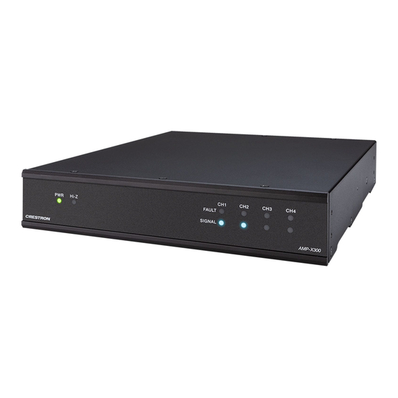
Crestron X Series Quick Start Manual

Crestron X Series Quick Start Manual

Hide thumbs Also See for X Series:

Advertisement

AMP-X75
X-Series Amplifier, 75 W
The Crestron®
AMP-X75
is a high performance, space saving, energy
efficient amplifier that's totally configurable, yet simple to use. Whether
installed in a rack, mounted on a wall, or placed on a table, the AMP-X75
is simple to specify and install in any configuration.
 
In the Box
1
AMP-X75, X-Series Amplifier, 75 W


Additional Items
4
Screw, 8-32 x 5/16 in., Flat Head, Phillips, Black (2055195)
4
Screw, 6-32 x 3/8 in., Undercut Head, Phillips (2055196)
2
Plate, Joining (2055198)
4
Foot, Adhesive, Black (2055200)
1
Fascia Plate with Tape, Quarter-Width (2058154)
1
Rack Ear, 1U, Quarter-Width (2058155)
1
Fascia Plate with Tape, Half-Width (2058156)
1
Rack Ear, 1U, Half-Width (2058157 )
1
Power cord (2055205)
1
Connector, Speaker (2055206)
2
Connector, Input (2055207)
1
Connector, 2-Pin (2003574)
 
Assemble
Prepare for Installation
The amplifier can be installed in a rack, mounted on a wall, or placed on
a table.
Rack Installation
Before an amplifier can be installed in a rack, rack ears must be
attached.
Single Amplifier
 1. Remove the protective plastic from the adhesive strip on the rear
side of the fascia plates.
 2. Press the fascia plates against the rack ears to attach them.
Quick Start
1

Advertisement

Table of Contents
loading
Need help?

Need help?

Do you have a question about the X Series and is the answer not in the manual?

Questions and answers

Subscribe to Our Youtube Channel

Summary of Contents for Crestron X Series

  • Page 1 Quick Start AMP-X75 X-Series Amplifier, 75 W The Crestron® AMP-X75 is a high performance, space saving, energy efficient amplifier that’s totally configurable, yet simple to use. Whether Assemble installed in a rack, mounted on a wall, or placed on a table, the AMP-X75 is simple to specify and install in any configuration.
  • Page 2 Quick Start AMP-X75 X-Series Amplifier, 75 W  3. Attach the rack ears to the amplifier with the four included  1. Place the amplifiers upside-down and adjacent to each other on a 6-32 x 3/8 in. screws. flat surface.  2. Use a Phillips screwdriver (not included) to gang the amplifiers together with three joining plates (two are included with each amplifier) and twelve 8-32 x 5/16 in.
  • Page 3 Quick Start AMP-X75 X-Series Amplifier, 75 W Surface Mount  3. Turn over the amplifier assembly and attach the rack ears to each side of the amplifier assembly with six 6-32 x 3/8 in. screws (four are Place the amplifier upside-down on a flat surface and attach the two included with each amplifier).
  • Page 4 Quick Start AMP-X75 X-Series Amplifier, 75 W Surface Placement Attach the four included feet if the amplifier is to be placed on a flat Install surface such as a table. Once assembled, the amplifier can be installed in a rack, mounted on a wall, or placed on a table.
  • Page 5 Quick Start AMP-X75 X-Series Amplifier, 75 W Mount on a Flat Surface Electrical Connection: “This product must be connected to an earthed mains socket-outlet.” Using two anchors (not included) and two mounting screws (not included), mount the device onto a flat surface such as a wall. Finland: “Laite on liitettävä...
  • Page 6 Quick Start AMP-X75 X-Series Amplifier, 75 W Place on a Flat Surface Place the amplifier on a flat surface such as a table. Connect Make the necessary connections as called out in the following diagrams. Connect power last. CAUTIONS:   Keep the device unplugged until all of the input and speaker wiring is complete.
  • Page 7: Quick Start

    AMP-X75 Quick Start X-Series Amplifier, 75 W...
  • Page 8: Input Wiring

    Quick Start AMP-X75 X-Series Amplifier, 75 W Speaker Mode Selection Switch Input Wiring The AMP-X75 can be configured to work with 4 Ω and 8 Ω (low Balanced and Unbalanced Audio impedance/LoZ) loads or constant voltage (high impedance) 70V/100V loads. The AMP-X75 can receive balanced audio through the terminal block connector and unbalanced audio through the terminal block connector  ...
  • Page 9: Signal Flow Diagram

    AMP-X75 Quick Start X-Series Amplifier, 75 W Signal Flow Diagram Refer to the following diagram for details on stereo, summed, bridged, and Hi-Z signal flow. Output Wiring Options The AMP-X75 can be configured for low impedance (LoZ) stereo or sum operation over two channels, mono bridged operation over one channel, or high impedance (70V or 100V) operation over one channel.
  • Page 10 Quick Start AMP-X75 X-Series Amplifier, 75 W 2 Channel up to 35 W Each Output (Low Impedance)
  • Page 11 Quick Start AMP-X75 X-Series Amplifier, 75 W 1 Channel up to 75 W Bridged Output (Low Impedance)
  • Page 12 Quick Start AMP-X75 X-Series Amplifier, 75 W 1 Channel up to 75 W Bridged Output (High Impedance)
  • Page 13: Operation

    Quick Start AMP-X75 X-Series Amplifier, 75 W Operation Observe the LED Indicators The LEDs on the front panel provide the following information: Configuration LED Indicator Color Meaning Each amplifier channel has its own gain control on the rear of the White The amplifier is operating normally.
  • Page 14: Important Instructions

    Quick Start AMP-X75 X-Series Amplifier, 75 W Important Instructions Instructions Importantes Important Safety Instructions Instructions de sécurité importantes WARNING: When using this product, basic precautions should always be Les avertissements: concernant l'utilisation de ce produit doivent followed, including the following: toujours être fondés sur les précautions fondamentales, notamment:  1.
  • Page 15: Product Label

    Visit the Product Page Product Label Scan the QR code to visit the product page. The product label is located on the bottom of the device. It displays SKU, ratings, and compliance related information. AMP-X75   www.crestron.com/model/6511136  ...
  • Page 16 Crestron disclaims any proprietary interest in the marks and names of others. Crestron is not responsible for errors in typography or photography.

This manual is also suitable for:

Amp-x75

Table of Contents