Chapters
Table of Contents

Subscribe to Our Youtube Channel
Related Manuals for Stahl isPAC HART 9196 Series


Summary of Contents for Stahl isPAC HART 9196 Series
- Page 1 Betriebsanleitung Operating instructions Additional languages www.stahl-ex.com DE EN HART-Anschlussboard HART Termination Board Reihe 9196 Series 9196...
- Page 3 Betriebsanleitung Additional languages www.stahl-ex.com HART-Anschlussboard Reihe 9196...
-
Page 4: Table Of Contents
Inhaltsverzeichnis Allgemeine Angaben ...................3 Hersteller ......................3 Angaben zur Betriebsanleitung ................3 Weitere Dokumente ....................3 Konformität zu Normen und Bestimmungen ............3 Erläuterung der Symbole ..................4 Symbole in der Betriebsanleitung ...............4 Warnhinweise .....................4 Symbole am Gerät ....................5 Sicherheitshinweise ....................5 Aufbewahrung der Betriebsanleitung ..............5 Sichere Verwendung ...................5 Funktion und Geräteaufbau ................6 Funktion ......................6... -
Page 5: De De
• Handbuch 9196 • Engineering Guide Weitere Sprachen, siehe www.stahl-ex.com. Konformität zu Normen und Bestimmungen Siehe Zertifikate und EG-Konformitätserklärung: www.stahl-ex.com. Das Gerät verfügt über eine IECEx-Zulassung. Siehe IECEx-Homepage: http://iecex.iec.ch/ Weitere nationale Zertifikate stehen unter dem folgenden Link zum Download bereit: http://www.r-stahl.com/downloads/certificates.html. -
Page 6: Erläuterung Der Symbole
Erläuterung der Symbole Erläuterung der Symbole Symbole in der Betriebsanleitung Symbol Bedeutung Tipps und Empfehlungen zum Gebrauch des Geräts Gefahr allgemein Gefahr durch explosionsfähige Atmosphäre Gefahr durch spannungsführende Teile Warnhinweise Warnhinweise unbedingt befolgen, um das konstruktive und durch den Betrieb bedingte Risiko zu minimieren. -
Page 7: Symbole Am Gerät
• Gerät nur bestimmungsgemäß und nur für den zugelassenen Einsatzzweck verwenden. • Bei Betriebsbedingungen, die durch die technischen Daten des Geräts nicht abgedeckt werden, unbedingt bei der R. STAHL Schaltgeräte GmbH rückfragen. • Für die Projektierung das Dokument "Installationsanleitung Schaltschrank" beachten (Download über www.stahl-ex.com, Produktdokumentation, Unterpunkt "Projektierung"). -
Page 8: 4 Funktion Und Geräteaufbau
Funktion und Geräteaufbau • Das Gerät enthält Bauteile, die durch elektrostatische Entladung beschädigt werden können. Vor Arbeiten am Gerät Körper an geerdeten Metallteilen entladen bzw. ein ESD-Ableitband anlegen. • Sicherstellen, dass die Bemessungsspannung beim Anschluss der Signalstromkreise um nicht mehr als 40 % überschritten wird. •... - Page 9 Technische Daten V102-Schnittstelle Erweiterungsstecker für weitere 16 Kanäle Anschluss Hilfsenergie Hilfsenergie 24 V DC X01-Schnittstelle Typ 9196/16H-xx0-01c: Eingang des Automatisierungssystems; Spannungssignal 1 ... 5 V Typ 9196/16H-xx0-04c: Eingang des Automatisierungssystems; Spannungssignal 1,72 ... 8,6 V X21-Schnittstelle Typ 9196/16H-xx0-01c: optionaler Anschluss von z.B. Schreibern. Nur für galvanisch getrennte Eingänge! Typ 9196/16H-xx0-04c: externer Jumper zur Funktionseinstellung...
-
Page 10: Technische Daten
1 - 5 V gemeinsame Masse Messumformer- zulässig speisegerät 9196/16H-XX0-04c 05674E01 Ausgang 4 - 20 mA 4 - 20 mA 4 - 20 mA gemeinsame Masse zulässig 9196/16H-XX0-04c 05675E01 Weitere technische Daten, siehe www.stahl-ex.com. HART-Anschlussboard 160901/9196601310 Reihe 9196 2015-08-17 BA00 III de 07... -
Page 11: Transport Und Lagerung
Projektierung Projektierung GEFAHR Explosionsgefahr durch zu hohe Temperatur im Schaltschrank! Nichtbeachten führt zu schweren oder tödlichen Verletzungen! • Schaltschrank so aufbauen und einrichten, dass er immer innerhalb des zulässigen Temperaturbereichs betrieben wird. • "Installationsanleitung Schaltschrank" sorgfältig beachten. Transport und Lagerung •... -
Page 12: 8.3 Installation
Montage und Installation 8.2.1 Montage / Demontage auf Hutschiene Montage • HART-Anschlussboard auf Hutschiene ansetzen und so aufschwenken, dass die Halterungsstege des HART-Anschlussboards auf der Hutschiene einrasten. 08058E00 08060E00 Demontage • Schraubendreher auf der Unterkante des HART-Anschlussboards ansetzen (1) und HART-Anschlussboard aus der Hutschiene hebeln. •... -
Page 13: Anschlüsse Von Feldgeräten Und Automatisierungssystem
Montage und Installation 8.3.1 Elektrische Anschlüsse GEFAHR Explosionsgefahr durch zu hohe Spannung! Nichtbeachten führt zu schweren oder tödlichen Verletzungen. • Gerät nur an Betriebsmittel mit interner Spannung U max. 253 V AC / 50 Hz anschließen. • Gerät nur an eigensichere Klemmen anschließen. HINWEIS Geräteausfall durch elektrostatisch überladene Bauelemente! Nichtbeachten kann Sachschaden verursachen! - Page 14 Montage und Installation Anschlussplan Kanal (I/0-Signal von (1 ... 5 V zum PLS) (4 … 20 mA zum Schreiber) Messumformer) Siehe Kapitel "Einstellungen am HART-Multiplexer 9192". Typ 9196/16H-xx0-03c für allgemeine Anwendungen Anschlussschema für 2-Leiter-Messumformer Variante A Im (+)-Versorgungszweig des PLS muss ein Widerstand > 250 Ω vorhanden sein. Eingang speisend 4 - 20 mA...
- Page 15 Montage und Installation Variante B Im (-)-Versorgungszweig des PLS muss ein Widerstand > 250 Ω vorhanden sein. Eingang speisend 4 - 20 mA HART 9196/16H-XX0-03c > 250 R 11338E Der (aktive) Eingang muss für HART-Kommunikation einen Eingangswiderstand zwi- schen 230 ... 600 Ω im Frequenzbereich von 500 Hz ... 10 KHz aufweisen. Der HART- Multiplexer wird parallel zum Messumformer angeschlossen.
- Page 16 Montage und Installation Anschlussschema für Stellungsregler 9196/16H-XX0-03c Ausgang 4 - 20 mA gemeinsame Masse zulässig Anschlussplan für Stellungsregler Kanal (I/0-Signal vom Stellungsregler) Siehe Kapitel "Einstellungen am HART-Multiplexer 9192". Typ 9196/16H-xx0-04c für allgemeine Anwendungen Anschlussschema für 2-Leiter-Messumformer Externer Hilfsenergie Jumper Eingang 1 - 5 V 2 Leiter 4 - 20 mA...
-
Page 17: Anschlüsse Am Hart-Multiplexer Typ 9192
Montage und Installation Anschlussplan für 2-Leiter-Messumformer Kanal (I/0-Signal von Messumformer) (1,72 ... 8,6 V zum PLS) (Jumper zwischen "+" und "-") Siehe Kapitel "Einstellungen am HART-Multiplexer 9192". Anschlussschema für Stellungsregler Ausgang 4 - 20 mA 4 - 20 mA 4 - 20 mA gemeinsame Masse zulässig... - Page 18 Montage und Installation 08047E01 Alle Eingangsleitungen Ch1 … 16 sind für DC-Signale über Kondensatoren entkoppelt. Bei einer gemeinsamen Verbindung von Eingangsleitungen muss beachtet werden, dass nur die "-" Pole miteinander verbunden sein dürfen (z.B. gemeinsame Masse in der PLS-Analog-Eingangskarte). HART-Anschlussboards mit 16 Kanälen 9196/16H-xx0-01c / -04c 9196/16H-xx0-03c 9185/..
-
Page 19: Einstellungen Am Hart-Multiplexer 9192
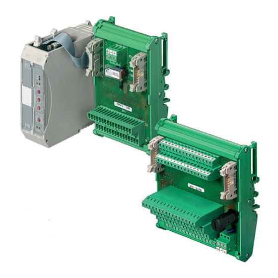
Parametrierung und Inbetriebnahme Gerätelement 9185/.. Wandler RS-485/RS-232 14-polige Flachbandleitung 9192/32-10-10 HART-Multiplexer Hilfsenergie-Anschluss 24 V Kanäle 1 … 16 Kanäle 17 … 32 Einstellungen am HART-Multiplexer 9192 Weitere Informationen zum HART-Multiplexer, siehe Datenblatt und/oder Be- triebsanleitung 9192. Typ Anschluss- Anzahl der Anzahl Kanäle Einstellung HART- RS-485-... -
Page 20: 10.1 Betrieb
Sicherungsabdeckung zulässig. *) Sicherungswechsel, siehe Kapitel "Sicherungswechsel" Wenn sich der Fehler mit den genannten Vorgehensweisen nicht beheben lässt: • An R. STAHL Schaltgeräte GmbH wenden. Zur schnellen Bearbeitung folgende Angaben bereithalten: • Typ und Seriennummer des Geräts • Kaufdaten •... -
Page 21: Reparatur
Auf der Internetseite "www.stahl-ex.com" im Menü "Downloads > Kundenservice": • Serviceschein herunterladen. • Serviceschein ausfüllen. • Gerät zusammen mit dem Serviceschein in der Originalverpackung an die R. STAHL Schaltgeräte GmbH senden. Entsorgung • Nationale und lokal gültige Vorschriften und gesetzliche Bestimmungen zur Entsorgung beachten. - Page 23 Operating instructions Additional languages www.stahl-ex.com HART Termination Board Series 9196...
- Page 24 Contents General Information ....................3 Manufacturer .......................3 Information regarding the operating instructions ..........3 Further documents ....................3 Conformity with standards and regulations ............3 Explanation of the symbols .................4 Symbols in these operating instructions .............4 Warning notes .....................4 Symbols on the device ..................5 Safety notes ......................5 Operating instructions storage ................5 Safe use ......................5...
-
Page 25: En En
• Engineering Guide For further languages, see www.stahl-ex.com. Conformity with standards and regulations See certificates and EC Declaration of Conformity: www.stahl-ex.com. The device has IECEx approval. See IECEx homepage: http://iecex.iec.ch/ Further national certificates can be downloaded via the following link: http://www.r-stahl.com/downloads/certificates.html. -
Page 26: Explanation Of The Symbols
Explanation of the symbols Explanation of the symbols Symbols in these operating instructions Symbol Meaning Tips and recommendations on the use of the device General danger Danger due to explosive atmosphere Danger due to energised parts Warning notes Warnings must be observed under all circumstances, in order to minimize the risk due to construction and operation. -
Page 27: Symbols On The Device
• Use the device in accordance with its intended and approved purpose only. • Always consult with R. STAHL Schaltgeräte GmbH if using the device under operating conditions which are not covered by the technical data. • Observe the document "Cabinet installation guide" for engineering (download from www.stahl-ex.com, product documentation, subitem "Engineering"). -
Page 28: 4 Function And Device Design
Function and device design • Ensure that the rated voltage is not exceeded by more than 40 % when connecting the signal circuits. • The interchangeable fuses of the device may only be replaced outside Zone 2, 22 or in a de-energised state. The operation is permitted only if the protective cover is screwed in correctly. - Page 29 Technical data X01 interface Type 9196/16H-xx0-01c: Input of automation system; voltage signal 1...5 V Type 9196/16H-xx0-04c: Input of automation system; voltage signal 1.72 ... 8.6 V X21 interface Type 9196/16H-xx0-01c: optional connection, e.g. of recorders. Only for galvanically isolated inputs! Type 9196/16H-xx0-04c: external jumper for functional setting "analogue input"...
-
Page 30: Technical Data
9196/16H-XX0-04c unit 05674E01 output 4 - 20 mA 4 - 20 mA 4 - 20 mA Common ground allowed 9196/16H-XX0-04c 05675E01 For further technical data, see www.stahl-ex.com. HART Termination Board 160901/9196601310 Series 9196 2015-08-17 BA00 III en 07... -
Page 31: Transport And Storage
Engineering Engineering DANGER Explosion hazard due to too high temperature in the cabinet! Non-compliance results in severe or fatal injuries! • Install and adjust the cabinet in such a way that it is always operated within the permissible temperature range. •... -
Page 32: 8.3 Installation
Mounting and installation 8.2.1 Mounting / dismounting on top hat rail Mounting • Position the HART termination board on top hat rail and swivel it such that the mounting webs of the HART termination board engage on the top hat rail. 08058E00 08060E00 Dismounting... -
Page 33: Connection Of Field Devices And Automation System
Mounting and installation 8.3.1 Electrical connections DANGER Explosion hazard caused by too high voltage! Non-compliance results in severe or fatal injuries. • Connect the device only to equipment with internal voltage U max. 253 V AC / 50 Hz. • Connect the device only to intrinsically safe terminals. NOTICE Device failure due to electrostatically overcharged components! Non-compliance can result in material damage! - Page 34 Mounting and installation Connection diagram Channel (I/0 signal of transmitter) (1 ... 5 V to PLS) (4 … 20 mA to recorder) See chapter "Settings on HART-multiplexer 9192". Type 9196/16H-xx0-03c for general use Connection diagram for 2-wire transmitter Variant A The (+) supply branch of the PLS must contain a resistor >...
- Page 35 Mounting and installation Variant B The (-) supply branch of the PLS must contain a resistor > 250 Ω. input powered 4 - 20 mA HART 9196/16H-XX0-03c > 250 R 11338E For HART communication, the (active) input must have an input resistance between 230 ...
- Page 36 Mounting and installation Connection diagram for positioner 9196/16H-XX0-03c output 4 - 20 mA Common ground allowed 11339E Connection diagram for positioner Channel (I/0 signal of positioner) See chapter "Settings on HART-multiplexer 9192". Type 9196/16H-xx0-04c for general use Connection diagram for 2-wire transmitter External Auxillary Jumper...
-
Page 37: Connections To Hart Multiplexer Type 9192
Mounting and installation Connection diagram for 2-wire transmitter Channel (I/0 signal of transmitter) (1.72 ... 8.6 V to PLS) (Jumper between "+" and "-") See chapter "Settings on HART-multiplexer 9192". Connection diagram for positioner output 4 - 20 mA 4 - 20 mA 4 - 20 mA Common ground... - Page 38 Mounting and installation 08047E01 All input lines Ch1 … 16 are decoupled for DC signals via capacitors. In case of common connection of input lines, make sure that only the "-" poles are connected to one another (e.g. common ground in the PLS analogue input card). HART termination board with 16 channels 9196/16H-xx0-01c / -04c 9196/16H-xx0-03c...
-
Page 39: Settings On Hart-Multiplexer 9192
Parameterization and commissioning Device component 9185/.. transducer RS-485/RS-232 14-pole ribbon cable 9192/32-10-10 HART-multiplexer Auxiliary power connection 24 V Channels 1 … 16 Channels 17 … 32 Settings on HART-multiplexer 9192 For further information on the-HART multiplexer, please refer to data sheet and/or the operating instructions 9192. -
Page 40: 10.1 Operation
*) Change of fuse, see chapter "Changing the fuse" If the error cannot be eliminated using the mentioned procedures: • Contact R. STAHL Schaltgeräte GmbH. For fast processing, have the following information ready: • Type and serial number of the device •... -
Page 41: Repair
"www.stahl-ex.com" under "Downloads > Customer service": • Download the service form. • Fill out the service form. • Send the device along with the service form in the original packaging to R. STAHL Schaltgeräte GmbH. Disposal • Observe national and local regulations and statutory regulation regarding disposal. - Page 43 Type 9192/32-10-10 The HART-Multiplexer Type 9192 is a nonincendive apparatus for installation in Non-Hazardous, Class I, Division 2 or Zone 2, Hazardous (Classified) Locations. Connector for Type 9196/***-***-**** HART-Multiplexer connector Connectors for supply The Connection board Type 9196 is a nonincendive apparatus for installation in Non-Hazardous, Class I, Division 2 or Zone 2, Hazardous (Classified) Locations.
- Page 44 Type 9192/32-10-10 Maximum supply current (at 18 V DC source): 9192/32-10-10 75 mA Connector for HART-Multiplexer Type 9196/***-***-*** connector Connectors for supply Connection board Type 9196/aaH-bbb-ccd a = numeral 16 for number of channels b = number or letter for automation system c = numeral for version d = letter for connecting technique The above devices may be located in non-hazardous locations or Division 2 / Zone 2 hazardous (Classified) locations.
Need help?
Do you have a question about the isPAC HART 9196 Series and is the answer not in the manual?
Questions and answers