Stahl 8186 Operating Instructions Manual
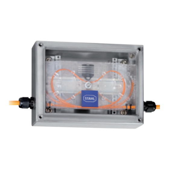
Optical fibre splice box
Hide thumbs
Also See for 8186:
- Operating instructions manual (21 pages) ,
- Operating instructions manual (37 pages)

Subscribe to Our Youtube Channel
Related Manuals for Stahl 8186


Summary of Contents for Stahl 8186
- Page 1 Betriebsanleitung/Operating Instructions Lichtwellenleiter- Spleisskassette Optical Fibre Splice Box > 8186...
- Page 3 Betriebsanleitung Lichtwellenleiter- Spleisskassette > 8186...
-
Page 4: Table Of Contents
Installation ......................5 Inbetriebnahme .....................7 Instandhaltung, Wartung und Störbeseitigung ............7 Zubehör und Ersatzteile ..................7 Entsorgung ......................7 EG-Konformitätserklärung ..................8 Allgemeine Angaben 2.1 Hersteller R. STAHL Schaltgeräte GmbH Am Bahnhof 30 74638 Waldenburg Germany Tel.: +49 7942 943-0 Fax: +49 7942 943-4333 Internet: www.stahl-ex.com... -
Page 5: Allgemeine Sicherheitshinweise
100 mW Frequenz 10 MHz, 100 MHz, 1 GHz, 10 GHz Mindestbiegeradius Einzeladern 40 mm Bündeladern 50 mm Material ABS / PC Abmessungen 210 x 104 x 10 mm (L x B x H) 203681 / 818660300010 Lichtwellenleiter- Spleisskassette 2010-10-20·BA00·III·de·00 8186... -
Page 6: Transport Und Lagerung
Abmessungen (L x B x H): 210 x 104 x 10 mm 1 - d 6,0 mm: Befestigung mit Schraube M5 2 - d 2,9 mm: Befestigung mit Senkschraube M3 3 - d 3,5 mm: Befestigung mit Schraube und Mutter M5 Lichtwellenleiter- Spleisskassette 203681 / 818660300010 8186 2010-10-20·BA00·III·de·00... -
Page 7: Übersicht Lichtwellenleiter-Spleisskassette
„IECEx Certificate of Conformity“ vorliegt. Vor dem Anschluss Alle Strahlungsquellen ausschalten und gegen unbefugtes Wiedereinschalten sichern. Sicherstellen, dass die Spleisskassette unversehrt und sauber ist. Sicherstellen, dass die angegebenen Mindestbiegeradien (Einzeladern 40 mm, Bündeladern 50 mm) eingehalten werden. 203681 / 818660300010 Lichtwellenleiter- Spleisskassette 2010-10-20·BA00·III·de·00 8186... - Page 8 Installation 11.1 Verlegearten Innerhalb der Spleisskassette können die Lichtwellenleiter wie folgt verlegt werden: 14060E00 14061E00 Variante 1 Variante 2 14062E00 14063E00 Variante 3 Variante 4 Lichtwellenleiter- Spleisskassette 203681 / 818660300010 8186 2010-10-20·BA00·III·de·00...
-
Page 9: Inbetriebnahme
Ist die Spleisskassette beschädigt, muss diese ausgetauscht werden. Eine Reparatur ist nicht zulässig. 14 Zubehör und Ersatzteile WARNUNG Verwenden Sie nur Original-Zubehör sowie Original-Ersatzteile der Fa. R. STAHL. 15 Entsorgung Die nationalen Vorschriften zur Abfallbeseitigung sind zu beachten. 203681 / 818660300010 Lichtwellenleiter- Spleisskassette 2010-10-20·BA00·III·de·00... -
Page 10: Eg-Konformitätserklärung
EG-Konformitätserklärung 16 EG-Konformitätserklärung Lichtwellenleiter- Spleisskassette 203681 / 818660300010 8186 2010-10-20·BA00·III·de·00... - Page 11 Operating Instructions Optical Fibre Splice Box > 8186...
- Page 12 Putting into Service ....................7 Maintenance, Overhaul and Repair ...............7 Accessories and Spare Parts ................7 Disposal .........................7 EC Declaration of Conformity ................8 General Information 2.1 Manufacturer R. STAHL Schaltgeräte GmbH Am Bahnhof 30 74638 Waldenburg Germany Tel.: +49 7942 943-0 Fax:...
-
Page 13: General Safety Instructions
10 MHz, 100 MHz, 1 GHz, 10 GHz Minimum bend radius Single fibres 40 mm Multifibre loose buffers 50 mm Material ABS / PC Dimensions 210 x 104 x 10 mm (L x W x H) 203681 / 818660300010 Optical Fibre Splice Box 2010-10-20·BA00·III·en·00 8186... -
Page 14: Transport And Storage
1 - d 6.0 mm: Fastening with M5 screw 2 - d 2.9 mm: Fastening with M3 countersunk head screw 3 - d 3.5 mm: Fastening with M5 screw and nut Optical Fibre Splice Box 203681 / 818660300010 8186 2010-10-20·BA00·III·en·00... -
Page 15: Overview Optical Fibre Splice Box
Make sure that the splice box is intact and clean. Make sure that the specified minimum bend radii (single fibre conductors 40 mm, multi-fibre conductors 50 mm) are observed. 203681 / 818660300010 Optical Fibre Splice Box 2010-10-20·BA00·III·en·00 8186... - Page 16 Installation 11.1 Types of Installation Inside the splice box, the optical fibre cables can be installed as follows: 14060E00 14061E00 Version 1 Version 2 14062E00 14063E00 Version 3 Version 4 Optical Fibre Splice Box 203681 / 818660300010 8186 2010-10-20·BA00·III·en·00...
-
Page 17: Putting Into Service
In case the splice box is damaged, it must be replaced. Repair work is not permitted. 14 Accessories and Spare Parts WARNING Use only R. STAHL accessories and spare parts. 15 Disposal The national waste disposal regulations have to be observed. -
Page 18: Ec Declaration Of Conformity
EC Declaration of Conformity 16 EC Declaration of Conformity Optical Fibre Splice Box 203681 / 818660300010 8186 2010-10-20·BA00·III·en·00... - Page 20 203681 / 818660300010 2010-10-20·BA00·III·de·en·00...
Need help?
Do you have a question about the 8186 and is the answer not in the manual?
Questions and answers