Table of Contents
Advertisement
Quick Links
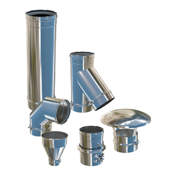
ENERVEX
POWERSTACK VENTING SYSTEM
Models EPSC
010.8030.1122
11.22
! WARNINGS
FAILURE TO FOLLOW THESE INSTALLATION INSTRUCTIONS
COULD CAUSE FIRE, CARBON MONOXIDE POISONING,
OR DEATH. IF YOU ARE UNSURE OF INSTALLATION
REQUIREMENTS, CALL THE PHONE NUMBER LISTED ON
THE BACK OF THESE INSTRUCTIONS.
A MAJOR CAUSE OF CHIMNEY RELATED FIRE IS FAILURE
TO MAINTAIN REQUIRED CLEARANCES (AIR SPACES) TO
COMBUSTIBLE MATERIALS. IT IS OF UTMOST
IMPORTANCE THAT THIS VENT SYSTEM BE INSTALLED ONLY
IN ACCORDANCE WITH THESE INSTRUCTIONS
UL File MH64314
ENERVEX Inc.
1685 Bluegrass Lakes
Parkway
Alpharetta, GA 30004
USA
READ AND SAVE THESE INSTRUCTIONS!
P: 770.587.3238
F: 770.587.4731
T: 800.255.2923
info@enervex.com
www.enervex.com
Installation & Operating Manual
Sizes 4–14" (100–350mm)
Special Gas Vent System for
Category II, III and IV Appliances
This installation manual will enable you to
obtain a safe, efficient and dependable
installation of this vent system. Please
read and understand these instructions
before beginning your installation.
Do not alter or modify the components of this
chimney system under any circumstances.Any
modification of alteration of the vent system or
approved accessories,including but not limited
to the appliance it is connected to, may void the
warranty, listings and approvals of this system
and could result in an unsafe and potentially
dangerous installation.
1. Examine all components for possible shipping
damage prior to installation.
2. Proper joint assembly is essential for a safe
installation. Follow these instructions exactly
as written. Check secureness of joints upon
completion of assembly.
3. This venting system must be free to
expand and contract. This venting system
must be supported in accordance with these
instructions.
4. Check for unrestricted vent movements
through walls, ceilings, and roof penetrations.
5. Different manufacturers have different joint
systems and adhesives. Do not mix pipe,
fittings, or joining methods from different
manufacturers.
Manufactured by ENERVEX Inc.
Advertisement
Table of Contents

Subscribe to Our Youtube Channel
Related Manuals for ENERVEX PowerStack EPSC


Summary of Contents for ENERVEX PowerStack EPSC
- Page 1 IMPORTANCE THAT THIS VENT SYSTEM BE INSTALLED ONLY manufacturers. IN ACCORDANCE WITH THESE INSTRUCTIONS READ AND SAVE THESE INSTRUCTIONS! Manufactured by ENERVEX Inc. UL File MH64314 ENERVEX Inc. P: 770.587.3238 1685 Bluegrass Lakes F: 770.587.4731 Parkway T: 800.255.2923...
- Page 2 010.8030.1222 12.22 UL File MH64314 This symbol shows that ENERVEX PowerStack EPSC venting systems are listed in the US and certified for Canada under Underwriters Laboratories Inc. file no. MH64314. IMPORTANT: READ THESE INSTRUCTIONS CAREFULLY PRIOR TO INSTALLATION. WARNING Failure to follow these installation instructions could cause FIRE, CARBON MONOXIDE POISONING, and/or DEATH.
-
Page 3: Table Of Contents
010.8030.1222 12.22 Content 1. GENERAL INFORMATION 5.6 Fan Adapter Termination ............17 6. STRUCTURAL SUPPORT AND GUIDE 1.1 Introduction ................. 4 COMPONENTS 1.2 Features ..................4 1.3 System Design And Calculations ..........4 6.1 Support Plate Assembly ............18 1.4 Underwriters Laboratories Listings ..........4 6.2 Horizontal Support .............. -
Page 4: General Information
Cat. II, III or IV appliances SHALL NOT be common vented with Cat. PowerStack EPSC is suitable for negative, neutral or positive I, natural draft appliances. This limitation can be ignored pressure applications and intended for use in a variety of... -
Page 5: Termination
010.8030.1222 12.22 outside the area in which the heating appliance connected 1.6 TERMINATION to it is located, it shall be provided with an enclosure having For EPSC systems used as Special Gas Vents, the systems a fire resistance equal to or greater than the fire rating of the shall terminate above the roof level in accordance with the floor, ceiling, wall or roof assemblies through which it passes. -
Page 6: Pipe Joint Assembly
010.8030.1222 12.22 1.10 PIPE JOINT ASSEMBLY Note 1: The values in Table 1-4 have not been confirmed by UL LLC. PowerStack components have a male-to-female joint system Note 2: Maximum distance between supports is 30 feet (9.1 m) with an integrated Elastomer Triple Lip Seal. The installation MAX. -
Page 7: Wall Penetration
010.8030.1222 12.22 The total continuous distance of the vent system from the collar. A condensate drain is also required for every 30 feet of appliance flue collar to the termination shall not exceed horizontal vent and at the bottom of a vertical stack. that specified in the appliance manufacturer’s installation instructions. -
Page 8: Vent Joint Assembly
010.8030.1222 12.22 1.18 VENT JOINT ASSEMBLY All EPSC components feature a simple push-fit joint design, allowing ease and speed of installation, while maintaining a secure and pressure tight joint. To assemble the joint, simply follow the steps below. 1. EPSC are always installed with the female spigot facing towards the termination and the male end facing towards the appliance. -
Page 9: Locking Band Assembly
010.8030.1222 12.22 1.19 LOCKING BAND ASSEMBLY The locking band has a unique profile and must be installed using the correct orientation. It MUST be located so the snap lock is only closed from left to right. 1. Attach the drawer to the latch See Fig. 1-4 2. -
Page 10: Connection And Adapters
ANSI 125/150 bolt flange attached at the other end. Can be connected to another ANSI 125/150 bolt flange whether on a generator, engine, boiler or other appliance. 2.3 APPLIANCE ADAPTERS ENERVEX supplies adapters for most common appliances. Fig 2-2: Flange Adapter Fig 2-3: Appliance Adapter... -
Page 11: Straight Lengths
010.8030.1222 12.22 3. STRAIGHT LENGTHS 3.1 PIPE LENGTHS The PowerStack EPSC is available in various standard nominal lengths: • 6” - Installed length = 4” (98mm) • 10” - Installed length = 9” (224mm) • 20” - Installed length =18” (474mm) •... -
Page 12: Adjustable Length
010.8030.1222 12.22 3.4 ADJUSTABLE LENGTHS The Adjustable Length consists of a slip section EPSC, the lower non-beaded end of which is designed preferably to be located into a standard length and must engage to a depth equivalent to at least half of the diameter of the diameter of the EPSC being used, Where pressure and moisture are required a special HD Locking Band &... -
Page 13: Hd Locking Band Assembly
010.8030.1222 12.22 3.5 HD LOCKING BAND ASSEMBLY The HD Locking Band has a unique profile and must be installed using the correct orientation. It MUST be located so the snap lock is only closed from left to right. 1. Screw toggle on the HD Lcking Band should be adjusted so that when the rod end is engaged in the the strike, the lever pin is between 5 and 10 deg past the centre line. -
Page 14: Tees, Elbows, Increasers, Offsets And Manifold, Drains
010.8030.1222 12.22 4. TEES, ELBOWS, INCREASERS, OFFSETS AND MANIFOLD, DRAINS 4.1 45° LATERAL TEE Designed to provide connection, a change of direction and cleaning access if required. Can also be used to enable header connections to be made. Fig 4-1: 45° Lateral Tee 4.2 90°... -
Page 15: Tee Cap
010.8030.1222 12.22 4.4 TEE CAP Used to close off the unused opening of Tees and branched elbows where used for cleaning access. It can also be used as an end cap in horizontal runs, or as an inspection fitting cover. 4.5 DRAIN TEE CAP The Drain Tee Cap is used as as a drain for vertical vents. -
Page 16: Terminations
010.8030.1222 12.22 5. TERMINATIONS 5.1 GENERAL An upward discharge (such as with an Exit Cone or Open Top) provides the most effective means of dispersing vent gases into the atmosphere and away from immediate surroundings. Such terminations however, will allow entry of rain unless there is upward flow at high velocity. -
Page 17: Fan Plate Adapter
Note: At present (2015), Underwriters Laboratories (UL) has no Safety Standards for these devices, so although they are shown in this Chimney Section document and condoned by ENERVEX and others, UL has not independently investigated this product. Storm Collar Flashing... -
Page 18: Structural Support And Guide Components
010.8030.1222 12.22 6. STRUCTURAL SUPPORT AND GUIDE COMPONENTS 6.1 SUPPORT PLATE ASSEMBLY The support plate assembly consists of a single top plate and a pair of bottom plates assembled around the central stack and bolted together using M10 hardware. Any standard length straight section can be used with the support plate assembly. -
Page 19: Wall Support
010.8030.1222 12.22 6.3 WALL SUPPORT The Wall Support consists of the same plate support as the support plate assembly, but includes wall support bracing. All hardware included with the assembly must be used when connecting the plates to the provided support brackets. The Wall Side Support must always be positioned so that it is on the load bearing side of the trapped support flange. -
Page 20: Full Ring / Half Ring
010.8030.1222 12.22 6.6 FULL RING / HALF RING The Flat Ring may also be used as an expansion guide by attachment to a suitable structural steel frame. For a support Full Ring cradle for horizontal run, half ring or Support Straps may be suspended by rods. -
Page 21: Centering Band
010.8030.1222 12.22 6.9 CENTERING BAND Designed to insure proper centering of the vent inside an existing masonry chimney. Should be used every 13 feet Flexible (4m). Steel Fig 6-10: Centering Band 6.10 SUPPORTING TEES AND ELBOWS Proper support of Elbows and Tees is critical. Both must be protected from thermal expansion and bending forces. -
Page 22: Roof Penetrations, Thimbles And Flashing
010.8030.1222 12.22 7. ROOF PENETRATIONS, THIMBLES AND FLASHING 7.1 UNVENTED INSULATED ROOF ASSEMBLY Chimney Cap The insulated penetration thimble, which does not include a pipe section, is primarily for the penetration of building roofs and walls of combustible construction. It can be installed with a wooden frame at a minimum of 1”... -
Page 23: Wall Penetration
010.8030.1222 12.22 7.2 WALL PENETRATION This Wall Penetration assembly is primarily used for wall penetration allowing a section to pass through a wall made of combustible material. It is used to maintain a minimum clearance between the combustible wall material and the Steel Plate vent section passing through the wall. -
Page 24: Misc. Components
The connection to the power venter is customized for the appropriate diameter. 8.2 OTHER TRANSITIONS ENERVEX supplies other types of custom-made transitions. Shown here is a step-transition from a standard 1/2” flanged vent to a larger 1/2” flanged vent or other object. - Page 25 010.8030.1222 12.22...
- Page 26 010.8030.1222 12.22...
- Page 27 010.8030.1222 12.22...
-
Page 28: Warranty
4) Damage is not a result of burning garbage, waste oil, #6 oil or any other prohibitive material in the appliance served by the venting system. 5) ENERVEX has supplied the entire chimney or exhaust system from boiler/engine outlet to the termination of the vent. The ENERVEX 15&1 Warranty applies to EPSC used in Residential/Commercial/Industrial/Institutional applications.
Need help?
Do you have a question about the PowerStack EPSC and is the answer not in the manual?
Questions and answers