Table of Contents
Advertisement
ENERVEX
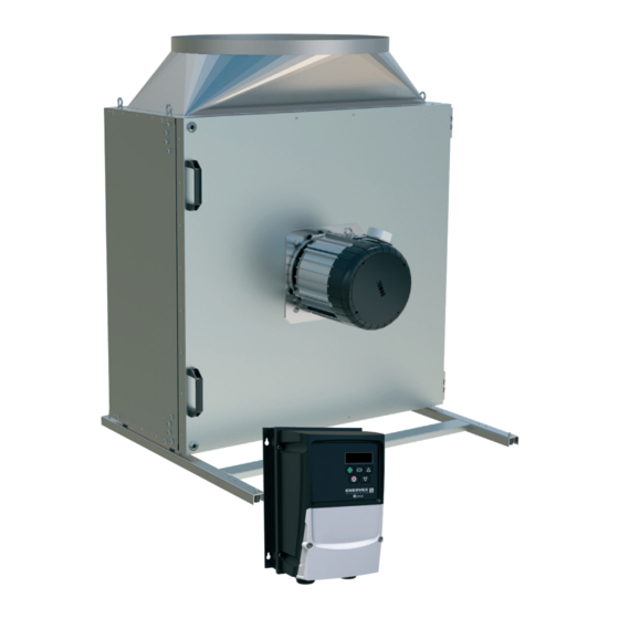
BEF 225-800X BOX VENTILATOR
010.1220.0719 01.21
File No. E479840
ENERVEX Inc.
1685 Bluegrass Lakes
Parkway
Alpharetta, GA 30004
USA
READ AND SAVE THESE INSTRUCTIONS!
P: 770.587.3238
F: 770.587.4731
T: 800.255.2923
info@enervex.com
www.enervex.com
Installation & Operating Manual
MAKE-UP AIR FOR LAUNDRY ROOMS
TYPE I & II RESIDENTIAL & COMMERCIAL
KITCHEN HOOD, BATHROOM EXHAUST
INTAKE AND EXHAUST APPLICATIONS
FOR MULTI-STORY BUILDINGS
CLOTHES DRYERS
Advertisement
Table of Contents

Related Manuals for ENERVEX BEF 225x


Summary of Contents for ENERVEX BEF 225x
- Page 1 TYPE I & II RESIDENTIAL & COMMERCIAL CLOTHES DRYERS KITCHEN HOOD, BATHROOM EXHAUST INTAKE AND EXHAUST APPLICATIONS FOR MULTI-STORY BUILDINGS READ AND SAVE THESE INSTRUCTIONS! File No. E479840 ENERVEX Inc. P: 770.587.3238 1685 Bluegrass Lakes F: 770.587.4731 Parkway T: 800.255.2923 Alpharetta, GA 30004 info@enervex.com...
- Page 2 010.1220.0719 01.21 UL File E479840 This symbol shows that ENERVEX BEFx Box Ventilators are listed under Category Code ZACT. Symbol Legend The following terms are used throughout this manual to bring TO REDUCE THE RISK OF FIRE, attention to the presence of potential hazards, or to important ELECTRICAL SHOCK OR INJURY TO information concerning the product.
-
Page 3: Table Of Contents
010.1220.0719 01.21 Content 1. GENERAL INFORMATION 1.1 Introduction ............4 1.3 Components ............4 1.4 Shipping ............5 1.5 Accessories ............5 1.6 Listings .............5 1.7 Warranty ............5 2. SPECIFICATIONS AND DIMENSIONS 2.1 Specifications ...........6 3. MECHANICAL INSTALLATION 3.1 Positioning ............7 3.2 Door Position ............8 3.3 Floor Or Roof Mounting ........9 3.4 Ceiling Mounting ..........9 3.5 Connection to Duct ...........10... -
Page 4: General Information
IP54 Protection Class. Sealed ball bearings. The motor is protected from overloading, blocking, over and under voltage, and over-heating by a factory programmed EDrive motor controller by ENERVEX for optimal operation of the ventilator. The BEFx Box Ventilator is a component in the MCAS Modulating Combustion Air System™, MDVS Mechanical... -
Page 5: Shipping
UL 705 Standard for Power Ventilators Edition 6 - Revision Date 2013/12/17 Complies with and meets Type B, Spark Resistant Construction per AMCA standard 99-0401 classifications of Spark Resistant Construction. 1.7 Warranty 2-year factory warranty (see back cover). Complete warranty conditions are available from ENERVEX Inc. -
Page 6: Specifications And Dimensions
2.1 Specifications BEF 315x BEF 355x BEF 450x BEF 500x BEF 560x BEF 630x BEF 710x BEF 800x BEF 225x Fan Type Centrifugal Motor EC - motor Voltage Con guration 1x120 / 3x240 V 3x240 / 3x480V 1x120 / 3x240 V... -
Page 7: Mechanical Installation
010.1220.0719 01.21 3. MECHANICAL INSTALLATION 3.1 Positioning The ventilator can be oriented in multiple positions. Acceptable ventilator orientations are shown in Fig 3. The BEFx can be installed indoors and outdoors without any modifications. Wherever the ventilor is installed, make sure there is space enough to open the access door to an angle of approximately 90°, as shown in Fig 4, and to access the locking screws. -
Page 8: Door Position
010.1220.0719 01.21 3.2 Door Position The ventilator can be oriented in multiple positions. Acceptable ventilator orientations are shown in Fig 3. The BEFx can be installed indoors and outdoors without any modifications. Wherever the ventilor is installed, make sure there is space enough to be able to open the access door to an angle of approximately 90°, as shown in Fig 4, and to access the locking screws. -
Page 9: Floor Or Roof Mounting
010.1220.0719 01.21 3.3 Floor Or Roof Mounting To minimize transfer of noise and vibration, the ventilator unit should be mounted on a level, stable and vibration-free surface. If mounting on a wooden surface, a cement tile should be placed on the floor prior to mounting as shown in Fig 5. -
Page 10: Connection To Duct
010.1220.0719 01.21 3.5 Connection To Duct The ventilator can be connected to a duct. To acheive maximum performance with minimal energy consumption, the ventilator should be connected to the duct system with the specified lengths of duct before and after the ventilator. NOTE: The distance “3 x D”... -
Page 11: Field Junction Box
010.1220.0719 01.21 Attach the gooseneck directly to the outlet collar of the fan unit. DO NOT use sheet metal screws or other fasteners that will penetrate the gooseneck and obstruct airflow. Building code prohibits the placement of mesh screens on the ventilator outlet because of the potential fire hazard from lint build-up. -
Page 12: Electrical Installation
010.1220.0719 01.21 4. ELECTRICAL INSTALLATION 4.2 Motor Controller All ENERVEX BEFx fans come with, and must use, a factory 4.1 General programmed EDrive motor controller with an enclosure rated to NEMA 4X/IP66 for indoor and outdoor installation. All wiring must be in compliance with the local codes or in their absence, with the National Electric Code, NFPA70. -
Page 13: Mounting Of Edrive Motor Controller
010.1220.0719 01.21 4.3 Mounting of EDrive Motor Controller Mount the EDrive motor controller in a location that is only accessible to qualified personal. The EDrive must be installed within 300 ft of the BEFx Fan. See Fig 12. For more information about the EDrive E3 please refer the Installation &... -
Page 14: Electrical Connection Of The Motor And Edrive
010.1220.0719 01.21 voltage transients, typically originating from lightning strikes or switching of high power equipment on the same supply. When carrying out a HiPot (Flash) test on an installation in which the drive is built, the voltage surge suppression components may cause the test to fail. To accommodate this type of system HiPot test, the voltage surge suppression components can be disconnected by removing the VAR screw After completing the HiPot test, the screw should... -
Page 15: Wiring Diagram Bef 225-800X / 3X208-480V
010.1220.0719 01.21 shipped with the fan. The wiring diagram reflects the use of DANGER this controller. Only qualified electrical personnel familiar Fan rotation can be changed on the EDrive by switching the with the construction and operation of attachment position of any two power leads. this equipment and the hazards involved should install, adjust, operate, or service this 4.9 Wiring Diagram - BEF 225-800x / 3X208-480V... -
Page 16: Installing A Proven Flow System
Correct direction of wheel rotation is critical. For more information about alternative safety system, please Reversed rotation will result in poor air performance, consult ENERVEX. motor overloading and possible burnout. AVERTISSEMENT La turbine doit impérativement tourner dans le bon sens. -
Page 17: Startup And Configuration
010.1220.0719 01.21 5. STARTUP AND CONFIGURATION 5.1 Managing the Keypad The EDrive is configured and its operation monitored via the keypad and display. Used to display real-time information, to access and exit parameter NAVIGATE edit mode and to store parameter changes Used to increase speed in real-time mode or to increase parameter values in parameter edit mode Used to decrease speed in real-time mode or to decrease parameter... -
Page 18: Changing Parameters
010.1220.0719 01.21 5.4 Read Only Parameter Access 5.5 Resetting Parameter 5.3 Changing Parameters Press and hold the Press and hold the To reset parameter Navigate button >2 Navigate button >2 values to their factory seconds seconds default settings, press and hold UP, DOWN and STOP buttons for >2 seconds. -
Page 19: Start Up Sequence (Auto Tune)
Draft Controller, which is the most common configuration for a BEFx Box Ventilator. Start up processes for other configurations are available from ENERVEX. Note, that one of the most important steps in the start up process is to activate “Auto Tune”. Any time a parameter change is taking place, the last part is always to activate “Auto Tune”. -
Page 20: Maintenance And Troubleshooting
No other maintenance is required. 6.3 SERVICE Available spare parts are shown in Section 6.4 Replacement Parts Ordering. The motor has sealed and permanently lubricated bearings. Bearing replacement should only be done by ENERVEX or an authorized motor repair shop. -
Page 21: Replacement Parts Ordering
010.1220.0719 01.21 6.4 REPLACEMENT PARTS ORDERING When ordering replacement parts, please have model number and part position number available. Fan Housing Impeller Impeller spacers Motor Support Legs Spacer Spacers Motor mounting plate (outside housing) Impeller mouting hardware Motor mount Impeller mouting hardware Motor mount Kit with Allen key for door locking screws and 4 Motor mount... -
Page 22: Warranty Terms
In addition, we promise the original user that we will replace ENERVEX and installed as part of the system. or repair as we may elect, any parts or parts of the ENERVEX This warranty is a two-way agreement. ENERVEX promises... - Page 23 010.1220.0719 01.21...
- Page 24 ENERVEX Inc. P: 770.587.3238 1685 Bluegrass Lakes F: 770.587.4731 Parkway T: 800.255.2923 Alpharetta, GA 30004 info@enervex.com www.enervex.com...
Need help?
Do you have a question about the BEF 225x and is the answer not in the manual?
Questions and answers