Unigas HR93A Manual Of Installation - Use - Maintenance
Progressive and fully-modulating gas - light oil burners
Hide thumbs
Also See for HR93A:
- Manual of installation, use and maintenance (56 pages) ,
- Manual (128 pages) ,
- Manual of installation - use - maintenance (140 pages)
Table of Contents
Advertisement
Quick Links
Advertisement
Table of Contents

Related Manuals for Unigas HR93A


Summary of Contents for Unigas HR93A
- Page 1 HR91A - HR92A HR93A HR512A - HR515A HR520A - HR525A Progressive and fully-modulating gas - light oil burners MANUAL OF INSTALLATION - USE - MAINTENANCE BURNERS - BRUCIATORI - BRULERS - BRENNER - QUEMADORES - ГОРЕЛКИ M039213CB Rel. 1.0 07/2010...
-
Page 2: Table Of Contents
C.I.B. UNIGAS - M03X213CA TABLE OF CONTENTS WARNINGS ................................3 PART I: INSTALLATION ............................5 GENERAL FEATURES ................................... 5 How to interpret the burner “Performance curve” ........................... 6 Checking the proper gas train size ..............................6 Burner model identification ................................6 Specifications .................................... -
Page 3: Warnings
WARNINGS THIS MANUAL IS SUPPLIED AS AN INTEGRAL AND ESSENTIAL PART OF THE PRODUCT AND MUST BE DELIVERED TO THE USER. INFORMATION INCLUDED IN THIS SECTION ARE DEDICATED BOTH TO THE USER AND TO PERSONNEL FOLLOWING PRO- DUCT INSTALLATION AND MAINTENANCE. THE USER WILL FIND FURTHER INFORMATION ABOUT OPERATING AND USE RESTRICTIONS, IN THE SECOND SECTION OF THIS MANUAL. - Page 4 DIRECTIVES AND STANDARDS 3b) FIRING WITH GAS, LIGHT OIL OR OTHER FUELS Gas burners GENERAL European directives: The burner shall be installed by qualified personnel and in com- - Directive 2009/142/EC - Gas Appliances; pliance with regulations and provisions in force; wrong installation Directive 2006/95/EC on low voltage;...
-
Page 5: Part I: Installation
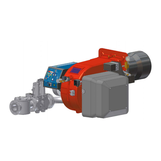
C.I.B. UNIGAS - M039213CB PART I: INSTALLATION GENERAL FEATURES Fig. 1 Mimic panel with startup switch Gas filter Gas proving system Gas valve group Cover Flange Blast tube-Combustion head group Oil pressure governor Actuator 10 Adjusting cams 11 Air intake... -
Page 6: How To Interpret The Burner "Performance Curve
Burners are identified by burner type and model. Burner model identification is described as follows. Type HR512A Model MG. HR91A - HR92A - HR93A - HR512A - HR515A - HR520A - HR525A (1) BURNER TYPE M - Natural gas G - Light oil... -
Page 7: Specifications
C.I.B. UNIGAS - M039213CB Specifications BURNER TYPE HR91A HR92A HR93A Output min. - max. kW 480 - 2670 480 - 3050 550 - 4100 Natural gas - Light oil Fuel (see next paragraph) Category min.- max. (Stm Gas rate 51 - 283... -
Page 8: Country And Usefulness Gas Categories
C.I.B. UNIGAS - M039213CB Country and usefulness gas categories COUNTRY CATEGORY ES GR SE NO CZ DK GB CY EE MT SK BG RO TR CH 2E( R ) B 2ELL... -
Page 9: Overall Dimensions
380 439 132 495 460 966 422 1311 877 434 304 344 307 360 505 M12 417 295 592 228 185 HR93A 100 1461 242 820 425 380 592 145 495 460 966 422 1401 967 434 304 344 447 360 505 M12 417 295 672... - Page 10 Burner flange Boiler recommended drilling template AA AB HR512A 50 1586 323 209 250 609 594 100 530 508 1056 446 1722 1079 643 492 M14 552 216 762 328 270 HR512A 65 1586 323 209 250 609 612 118 530 508 1056 446 1692 1049 643 492 M14 552 292 762 328 270 HR512A 80 1586 323 209 250...
-
Page 11: Performance Curves
C.I.B. UNIGAS - M039213CB Performance Curves HR91A HR92A 1200 1600 2000 2400 2800 3200 1200 1600 2000 2400 2800 HR93A HR512A 500 1000 1500 2000 2500 3000 3500 4000 4500 1500 2500 3500 4500 HR515A HR520A 1500 2500 3500 4500... -
Page 12: Pressure In The Network - Gas Rate Curves
C.I.B. UNIGAS - M039213CB Pressure in the network - gas rate curves HR91A HR92A Rp 2 (50) Rp 2 (50) DN65 DN65 DN80 DN80 DN100 DN100 HR93A HR512A Rp 2 (50) Rp 2 (50) DN65 DN65 DN80 DN80 DN100 DN100... -
Page 13: Mountings And Connections
C.I.B. UNIGAS - M039213CB MOUNTINGS AND CONNECTIONS Packing The burners are despatched wooden cages whose dimensions: 9xA series: 1730mm x 1280mm x 1020mm (L x P x H) 5xxA series: 1720mm x 1500mm x 1150mm (L x P x H) ... -
Page 14: Matching The Burner To The Boiler
C.I.B. UNIGAS - M039213CB Keys Burner Fixing nut Washer Ceramic fibre plait Stud bolt Blast tube Matching the burner to the boiler The burners described in this manual have been tested with combustion chambers that comply with EN676 regulation and whose dimensions are described in the diagram . -
Page 15: Gas Train Connections
C.I.B. UNIGAS - M039213CB Gas train connections The diagrams show the components of the gas train included in the delivery and which must be fitted by the installer.The diagrams are in compliance with the current laws. ATTENTION: BEFORE EXECUTING THE CONNECTIONS TO THE GAS PIPE NETWORK, BE SURE THAT THE MANUAL CUTOFF VALVES ARE CLOSED. -
Page 16: Assembling The Gas Grain
C.I.B. UNIGAS - M039213CB Assembling the gas grain gas supply network ”direction” arrows for installation Keys 1A..1E Gasket Gas filter Gas valves group Bellows unit Manual valve Fig. 5 - Example of gas train To mount the gas train, proceed as follows: 1-a) in case of threaded joints: use proper seals according to the gas used;... -
Page 17: Siemens Vgd20
C.I.B. UNIGAS - M039213CB MULTIBLOCDUNGS MBC1900-3100-5000SE (Flanged valves group) Mounting 1. Insert setscrews A 2. Insert seals 3. Insert setscrews B 4. Tighten setscrews A + B. Ensure correct seating of the seal! 6. After installation, perform leakage and functional test. -
Page 18: Pressure Adjusting Range
C.I.B. UNIGAS - M039213CB Fig. 13 Pressure adjusting range The pressure adjusting range, downstream the gas valves group, changes according to the spring provided with the valve group. DUNGS MBC..SE Siemens SKP actuator Keys 1 spring 2 cap DUNGS MBC valves:... -
Page 19: Hydraulic Diagrams For Light Oil Supplying Circuits
C.I.B. UNIGAS - M039213CB Hydraulic diagrams for light oil supplying circuits Fig. 14 - Gravity circuit Fig. 15 - Ring circuit Fig. 16 - Suction circuit Manual valve Light oil filter Light oil feeding pump One way valve Flexible hoses Relief valve NOTE: in plants where gravity or ring feed systems are provided, install an automatic interception device (see n. -
Page 20: Installation Diagram Of Light Oil Pipes
C.I.B. UNIGAS - M039213CB Installation diagram of light oil pipes PLEASE READ CAREFULLY THE “WARNINGS” CHAPTER AT THE BEGINNING OF THIS MANUAL. From tank To tank Fig. 17 - Double-pipe system The burner is supplied with filter and flexible hoses, all the parts upstream the filter and downstream the return flexible hose, must be installed by the customer. -
Page 21: Light Oil Pumps
C.I.B. UNIGAS - M039213CB line to bleed). To avoid damages inject some lubrication oil into the vacuum inlet. Care must be taken when installing the pump not to force the pump shaft along its axis or laterally to avoid excessive wear on the joint, noise and overloading the gears. -
Page 22: Assembling The Light Oil Flexible Hoses
C.I.B. UNIGAS - M039213CB Assembling the light oil flexible hoses To connect the flexible light oil hoses to the pump, proceed as follows, according to the pump provided: remove the closing nuts A and R on the inlet and return connections;... -
Page 23: Rotation Of Fan Motor And Pump Motor
C.I.B. UNIGAS - M039213CB Electrical Wiring Diagram for Burners Fitted with Printed Circuit High-low flame burners Electric motor connection Probes connection Fully modulating burners RWF40 >>> Power supply terminal board Terminal board for connections on printed circuit Rotation of fan motor and pump motor Once the electrical connection of the burner is executed, remember to check the rotation of the motor. -
Page 24: Adjustments
C.I.B. UNIGAS - M039213CB ADJUSTMENTS Combustion head gas pressure curves depending on the flow rate Curves are referred to pressure = 0mbar in the combustion head! The curves referred to the gas pressure in the combustion head, depending on the gas flow rate, are referred to the burner properly adjusted (percentage of residual O in the flues as shown in the “Recommended combustion values”... -
Page 25: Pressure In Combustion Head - Gas Rate Curves
C.I.B. UNIGAS - M039213CB Pressure in combustion head - gas rate curves HR91A HR92A 100 120 140 160 180 200 220 240 260 280 300 40 60 80 100 120 140 160 180 200 220 240 260 280 300 320 340... -
Page 26: Adjustments
C.I.B. UNIGAS - M039213CB Adjustments ATTENTION: before starting the burner up, be sure that the manual cutoff valves are open and check that the pres- sure upstream the gas train complies the value quoted on paragraph “Technical specifications”. Be sure that the mains switch is closed. -
Page 27: Adjustments - Brief Description
C.I.B. UNIGAS - M039213CB Adjustments - brief description Adjust the air and gas flow rates at the maximum output (“high flame”) first, by means of the air damper and the adjusting cam respec- tively. Check that the combustion parameters are in the suggested limits. -
Page 28: Air And Gas Flow Rate Settings By Means Of Berger Stm30../Siemens Sqm40.. Actuator
C.I.B. UNIGAS - M039213CB Air and Gas Flow Rate Settings by means of Berger STM30../Siemens SQM40.. actuator Siemens SQM40 mensions Dimensions in SQM4... Berger STM30 Actuator cams High flame Stand-by and Ignition Low flame - gas Low flame - oil (SQM40..) Low flame - oil (STM30..) -
Page 29: Adjustment By The Siemens Sql33.. Actuator
C.I.B. UNIGAS - M039213CB 10 Only if necessary, change the combusiton head position: to let the burner operate at a lower output, loose the VB screw and move progressively back the combustion head towards the MIN position, by turning clockwise the VRT ring nut. Fasten VB screw when the adjustment is accomplished. - Page 30 C.I.B. UNIGAS - M039213CB picture) to lock the adjusting cam. SQL33.. actuator cams A = (red) cam locking lever for “high flame” S = (green) cam locking lever for “stand-by and ignition” BF1 = Low flame (GAS) BF2 = Low flame (OIL) F = plastic cam go on adjusting air and gas flow rates: check, continuosly, the flue gas analisys, as to avoid combustion with little air;...
- Page 31 C.I.B. UNIGAS - M039213CB “MAX” head position “MIN” head position Attention! if it is necessary to change the head position, repeat the air and gas adjustments described above. 12 the air and gas rate are now adjusted at the maximum output, go on with the point to point adjustment on the SV1 adjusting cam...
-
Page 32: Calibration Of Air And Gas Pressure Switches
C.I.B. UNIGAS - M039213CB Calibration of air and gas pressure switches The air pressure switch locks the control box if the air pressure is not the one requested. If it happens, unlock the burner by means of the control box unlock pushbutton, placed on the burner control panel. -
Page 33: Adjusting Light Oil Flow Rate
C.I.B. UNIGAS - M039213CB Adjusting light oil flow rate The light oil flow rate can be adjusted choosing a by-pass nozzle that suits the boiler/utilisation output and setting the delivery and return pressure values according to the ones quoted on the chart below and the diagram on Fig. 21 (as far as reading the pressure values, see next paragraphs). -
Page 34: Oil Flow Rate Settings By Means Of Berger Stm30../Siemens Sqm40.. Actuator
C.I.B. UNIGAS - M039213CB Oil Flow Rate Settings by means of Berger STM30../Siemens SQM40.. actuator Once the air and gas flow rates are adjusted, turn the burner off, switch it on again by turning the CM switch to the oil operation (OIL, on the burner control panel (see page 38). -
Page 35: Adjustment By The Siemens Sql33.. Actuator
C.I.B. UNIGAS - M039213CB 14 Move again the low flame cam towards the minimum to meet the next screw on the adjusting cam and repeat the previous step; go on this way as to reach the desired low flame point. - Page 36 C.I.B. UNIGAS - M039213CB Fig. 26 Pressure gauge port Fig. 25 in order to get the maximum oil flow rate, adjust the pressure (reading its value on the PG pressure gauge) without changing the air flow rate set during the gas operation adjustments (see prevoius paragraph): checking always the combustion parameters, the adjustment is to be performed by means of the SV2 adjusting cam screw (see picture) when the cam has reached the high flame position.
-
Page 37: Oil Circuit
C.I.B. UNIGAS - M039213CB Oil circuit The fuel is pushed into the pump 1 to the nozzle 3 at the delivery pressure set by the pressure governor. The solenoid valve 2 stops the fuel immission into the combustion chamber. The fuel flow rate that is not burnt goes back to the tank through the return circuit. The spill-back nozzle is feeded at constant pressure, while the return line pressure is adjusted by means of the pressure governor controlled by an actuator coupled to an adjusting cam. -
Page 38: Part Ii: Operation
C.I.B. UNIGAS - M039213CB PART II: OPERATION LIMITATIONS OF USE THE BURNER IS AN APPLIANCE DESIGNED AND CONSTRUCTED TO OPERATE ONLY AFTER BEING CORRECTLY CONNEC- TED TO A HEAT GENERATOR (E.G. BOILER, HOT AIR GENERATOR, FURNACE, ETC.), ANY OTHER USE IS TO BE CONSIDE- RED IMPROPER AND THEREFORE DANGEROUS. - Page 39 C.I.B. UNIGAS - M039213CB The burner is now operating, meanwhile the actuator goes to the high flame position and, after some seconds, the two-stage ope- ration begins; the burner is driven automatically to high flame or low flame, according to the plant requirements.
-
Page 40: Part Iii: Maintenance
C.I.B. UNIGAS - M039213CB PART III: MAINTENANCE At least once a year carry out the maintenance operations listed below. In the case of seasonal servicing, it is recommended to carry out the maintenance at the end of each heating season; in the case of continuous operation the maintenance is carried out every 6 months. -
Page 41: Inspection And Replacement Of The Multibloc Dungs Mbc
C.I.B. UNIGAS - M039213CB Inspection and replacement of the MULTIBLOC DUNGS MBC..SE filter (Threaded valves group) Inspect the filter at least once a year. Change the filter, if pressure value between pressure connections 1 and 2 is grea- ther than 10 mbar. -
Page 42: Removing The Oil Gun, Replacing The Nozzle And The Electrodes
C.I.B. UNIGAS - M039213CB Removing the oil gun, replacing the nozzle and the electrodes ATTENTION: avoid the electrodes to get in touch with metallic parts (blast tube, head, etc.), otherwise the boiler operation would be compromised. Check the electrodes position after any intervention on the combustion head. -
Page 43: Troubleshooting
C.I.B. UNIGAS - M039213CB TROUBLESHOOTING CAUSE / FAULT MAIN SWITCH OPEN ABSENCE OF GAS MINIMUM GAS PRESSURE SWITCH FAULT OR BAD SETTING BOILER THERMOSTATS OPEN OVERLOAD TRIPPED INTERVENTION FUSES INTERVENTION ... -
Page 44: Burner Exploded View
BURNER EXPLODED VIEW DESCRIPTION DESCRIPTION DESCRIPTION ITEM ITEM ITEM FLANGE 15.10 AIR PRESSURE SWITCH 21.3 COVER AIR INLET CONE 15.10.1 THREADED GAS PIPE 22.4 PRESSURE GAUGE RING NUT 15.10.2 AIR PRESSURE SWITCH 22.7 ADJUSTING CAM PLATE 15.10.3 PRESSURE SWITCH BRACKET 22.7.14 ADJUSTING CAM FOIL BUTTERFLY GAS VALVE 15.12... -
Page 46: Spare Parts
C.I.B. UNIGAS - M039213CB SPARE PARTS Desription Code HR91A HR92A HR93A CONTROL BOX 2020448 2020448 2020448 IGNITION ELECTRODE 2080292 2080292 2080292 OIL FILTER 2090018 2090018 2090018 GAS FILTER - Rp 2 2090119 2090119 2090119 GAS FILTER - DN65 2090117 2090117... - Page 47 C.I.B. UNIGAS - M039213CB Desription Code HR512A HR515A HR520A HR525A CONTROL BOX 2020448 2020448 2020448 2020448 IGNITION ELECTRODE 2080292 2080292 2080292 2080292 OIL FILTER 2090018 2090018 2090018 2090018 GAS FILTER - Rp 2 2090119 2090119 2090119 2090119 GAS FILTER - DN65...
-
Page 48: Wiring Diagrams
C.I.B. UNIGAS - M039213CB WIRING DIAGRAMS ATTENTION: 1 - Electrical supply 400V 50Hz 3N a.c. 2 - Don’t reverse phase with neutral 3 - Ensure to the burner a proper hearthing Please, see the attached wiring diagram. Burners not fitted with printed circuit... -
Page 49: Appendix
APPENDIX consent to start-up by means of the thermostat or pressostat "R" SIEMENS LFL 1.3.. CONTROL BOX start-up program Automatic programme in the event of interruption and indication of posi- normal burner operation tion when interrupted regulation stop caused by "R" By default, in the event of any kind of interruption, the flow of fuel is imme- diately interrupted. - Page 50 2nd safety time; at the end of the second safety time the main bur- test 1300 µA ner should be lit by means of the pilot. At the end of this period, terminal Max.length of connecting cable 17 is dead and therefore the pilot burner will be out. normal cable (laid separately**) 100m Interval;...
- Page 51 interval for creating current between terminals 19 and 20 input for raising QRA detector voltage to test level post-ventilation time input for excitation of flame relay during flame detector test interval between startup consent and current created at circuit (contact XIV) and during safety time (contact IV) terminal 7 Do not press EK for more than 10 seconds duration of start-up...
- Page 52 C.I.B. UNIGAS S.p.A. Via L.Galvani, 9 - 35011 Campodarsego (PD) - ITALY Tel. +39 049 9200944 - Fax +39 049 9200945/9201269 web site: www.cibunigas.it - e-mail: cibunigas@cibunigas.it Note: specifications and data subject to change. Errors and omissions exceptd.
Need help?
Do you have a question about the HR93A and is the answer not in the manual?
Questions and answers