Table of Contents
Advertisement
Quick Links
Advertisement
Table of Contents

Related Manuals for Advantech MIX-Q670A1


Summary of Contents for Advantech MIX-Q670A1
- Page 1 MIX-Q670A1...
- Page 2 E21877 Revised Edition V2 March 2023 Copyright Notice This document is copyrighted, 2023. All rights are reserved. The original manufacturer reserves the right to make improvements to the products described in this manual at any time without notice. No part of this manual may be reproduced, copied, translated, or transmitted in any form or by any means without the prior written permission of the original manufacturer.
-
Page 3: Table Of Contents
Contents Chapter 1 Product overview Package contents ................. 1-1 Features ..................1-1 1.3 Specifications ................1-2 Chapter 2 Motherboard informatio Before you proceed ..............2-1 Motherboard layout ..............2-2 Screw size ..................2-4 2.3.1 Component side .............. 2-4 2.3.2 Solder side ..............2-5 Central Processing Unit (CPU) ........... - Page 4 Contents 3.3.8 AMT Configuration ............3-9 3.3.9 PCH-FW Configuration ........... 3-9 3.3.10 NVMe Configuration ............3-9 3.3.11 Power Management ............3-10 3.3.12 Digital IO Port Configuration ......... 3-10 Chipset menu ................3-10 3.4.1 System Agent (SA) Configuration ......... 3-11 3.4.2 PCH-IO Configuration ........... 3-11 Security menu ................3-11 3.5.1 Administrator Password ..........3-12 3.5.2 User Password ..............
-
Page 5: Chapter 1 Product Overview
Chapter 1 Product overview Package contents Check your industrial motherboard package for the following items. 1 x Industrial Motherboard 1 x SATA Cable 1 x I/O Shield NOTE: If any of the above items is damaged or missing, contact your distributor or sales representative immediately. -
Page 6: Specifications
Up to 4096 x 2160 @ 60 Hz LVDS Up to 1920 x 1080 @60 Hz, Daul Channel 18/24 bit co-layout with eDP Up to 1920 x 1080 @ 60 Hz co-layout with LVDS Backlight control (continued on the next page) MIX-Q670A1... - Page 7 Internal I/O Storage 2 x SATA (6.0Gb/s) ports 1 x M.2 M key (2280), [PCIex4/NVMe; Gen3] Serial port 1 x RS-232/422/485 (supports 5V/12V/RI option) 1 x RS-232 1 x USB 3.2 Gen 1 header (supports additional 2 USB3.2 Gen1 ports) Display I/O 40-pin LVDS/eDP connector x 1 with Inverter (Default LVDS) 1 x CPU Fan header (4-pin)
- Page 8 MIX-Q670A1...
-
Page 9: Chapter 2 Motherboard Informatio
Chapter 2 Motherboard information Before you proceed Take note of the following precautions before you install motherboard components or change any motherboard settings. CAUTION! • Unplug the power cord from the wall socket before touching any component. • Before handling components, use a grounded wrist strap or touch a safely grounded object or a metal object, such as the power supply case, to avoid damaging them due to static electricity. -
Page 10: Motherboard Layout
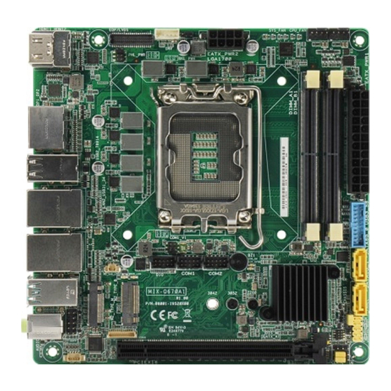
Place this side towards the rear USB2_78914 of the chassis LGA1700 Intel ® LAN2_USB31_34 219LM COM1_V1 LAN1_USB31_12 BATTERY_H LED_+5V LED_+5VSB COM1 COM2 Intel ® USB31_78910 Q670E 3042 3052 2280 DIS_ME AUDIO ATX_AT DEBUG 256Mb BIOS AAFP PCIEX16 AMP_CON CLRTC 16 15 MIX-Q670A1... - Page 11 Connectors/Jumpers/Slots Page LVDS T-con IC Power selection jumper (PNL_PWR) 2-16 eDP/LVDS connector 2-26 LVDS Panel Backlight Power header (INV) 2-25 LVDS Panel Power selection jumper (3-pin BKL_PWR) 2-14 ATX Power connectors (24-pin EATX_PWR1, 8-pin EATX_PWR2) 2-18 Intel LGA1700 CPU socket ®...
-
Page 12: Screw Size
Screw size 2.3.1 Component side 166.45 165.08 163.19 161.32 159.62 153.27 150.73 139.94 134.75 102.93 88.44 86.84 75.32 75.10 71.55 61.77 59.14 50.64 45.45 39.44 39.36 33.29 16.75 20.94 14.87 19.19 11.84 10.49 10.49 7.15 0.00 33.40 MIX-Q670A1... -
Page 13: Solder Side
2.3.2 Solder side 165.10 165.10 151.37 125.84 118.13 106.84 110.89 104.84 100.89 90.89 68.84 66.84 47.84 46.45 33.02 10.16 0.00 Chapter 2: Motherboard information... -
Page 14: Central Processing Unit (Cpu)
Return Merchandise Authorization (RMA) requests only if the motherboard comes with the cap on the LGA1700 socket. • The product warranty does not cover damage to the socket contacts resulting from incorrect CPU installation/removal, or misplacement/loss/ incorrect removal of the PnP cap. MIX-Q670A1... -
Page 15: Installing The Cpu
2.4.1 Installing the CPU CAUTION! • Ensure that you install the correct CPU designed for LGA1700 socket only. DO NOT install a CPU designed for LGA1155, LGA1156, LGA1151, and LGA1200 sockets on the LGA1700 socket. • ASUS will not cover damages resulting from incorrect CPU installation/ removal, incorrect CPU orientation/placement, or other damages resulting from negligence by the user. - Page 16 MIX-Q670A1...
-
Page 17: Cpu Heatsink And Fan Assembly Installation
2.4.2 CPU heatsink and fan assembly installation IMPORTANT: Apply Thermal Interface Material to the CPU cooling system and CPU before you install the cooling system, if necessary. CAUTION! Ensure to remove the CPU Socket lever protector on the lever latch before installing the cooling system, failure to do so may cause damages to your system. - Page 18 To uninstall the CPU heatsink and fan assembly MIX-Q670A1 2-10...
-
Page 19: System Memory
System memory The motherboard comes with Small Outline Dual Inline Memory Modules (SO- DIMM) slots designed for DDR5 (Double Data Rate 5) memory modules. CAUTION! A DDR5 memory module is notched differently from a DDR, DDR2, DDR3, or DDR4 module. DO NOT install a DDR, DDR2, DDR3, or DDR4 memory module to the DDR5 slot. -
Page 20: Installing A Dimm
2.5.1 Installing a DIMM To remove a DIMM MIX-Q670A1 2-12... -
Page 21: Jumpers
Jumpers Clear RTC RAM (CLRTC) This jumper allows you to clear the Real Time Clock (RTC) RAM in CMOS. You can clear the CMOS memory of date, time, and system setup parameters by erasing the CMOS RTC RAM data. The onboard button cell battery powers the RAM data in CMOS, which include system setup information such as system passwords. - Page 22 ATX mode AT mode (Default) Description Description Pins 1-2 (Default) ATX mode AT mode NOTE: Jumper setting of ATX_AT should be consistent with the setting of Power Mode in BIOS. Refer to section 3.3.11 Power Management in Chapter MIX-Q670A1 2-14...
- Page 23 Chassis intrusion header (4-1 pin CHASSIS) This header is for a chassis-mounted intrusion detection sensor or switch. Connect one end of the chassis intrusion sensor or switch cable to this header. The chassis intrusion sensor or switch sends a high-level signal to this header when a chassis component is removed or replaced.
- Page 24 ME Jumper (3-pin DIS_ME) ® This jumper allows you to force the Intel Management Engine (ME) to boot ® from recovery mode when ME becomes corrupted. eDP/LVDS T-con IC Power jumper (6-pin PNL_PWR) PNL_PWR +12V (Default) Setting Pins 1-2 (Default) +12V MIX-Q670A1 2-16...
-
Page 25: Connectors
Connectors 2.7.1 Rear panel connectors HDMI™ ports. These ports are for a High-Definition Multimedia Interface (HDMI™) connectors, and are HDCP compliant allowing playback of HD DVD, Blu-ray, and other protected content. DisplayPorts. These ports are for DisplayPort-compatible devices. USB 2.0 ports. These Universal Serial Bus (USB) ports are for USB 2.0 devices. -
Page 26: Internal Connectors
IMPORTANT: • For a fully configured system, we recommend that you use a power supply unit (PSU) that complies with ATX 12 V Specification 2.0 (or later version) and provides a minimum power of 330W. • We recommend that you use a PSU with higher power output when configuring a system with more power-consuming devices. The system may become unstable or may not boot up if the power is inadequate. MIX-Q670A1 2-18... - Page 27 BIOS Programmable header (8-pin SPI_1) Use this header to flash the BIOS ROM. SPI_1 (NC) (NC) S_SPI_MISO_1Q S_SPI_MOSI_1Q S_SPI_CS0#Q S_SPI_CLK_1Q +3V_SPI PIN 1 CPU and System Fan headers (4-pin CPU_FAN, 4-pin SYS_FAN) Connect the fan cables to the fan headers on the motherboard, ensuring that the black wire of each cable matches the ground pin of the header.
- Page 28 Audio Amplfier connector (4-pin AMP_CON) This connector is for an internal stereo amplifier speakers support (2W/4 via WtoB header). AMP_CON PIN 1 Battery connector (2-pin BATTERY_H) This connector is for the lithium CMOS battery. BATTERY_H PIN 1 MIX-Q670A1 2-20...
- Page 29 System Panel header (10-1 pin F_PANEL) This header supports several chassis-mounted functions. F_PANEL (NC) RSTCON#_PANEL F_PWRBTN# P_LED - HDD_LED - HDD_LED + P_LED+ PIN 1 • System Power LED header (2-pin +PWR_LED-) The 2-pin pin headers allow you to connect the System Power LED. The System Power LED lights up when the system is connected to a power source, or when you turn on the system power, and blinks when the system is in sleep mode.
- Page 30 HD audio standard. Connect one end of the front panel audio I/O module cable to this header. AAFP PIN 10 PIN 9 A_LINE2_L A_JD_LINE2 A_JD_FRONT A_LINE2_R A_JD_MIC2 A_MIC2_R (NC) A_MIC2_L A_GND PIN 2 PIN 1 IMPORTANT: We recommend that you connect a high-definition front panel audio module to this header to avail of the motherboard’s high-definition audio capability. MIX-Q670A1 2-22...
- Page 31 USB 3.2 Gen 1 header (20-1 pin USB3_56) This header allows you to connect a USB 3.2 Gen 1 module for additional USB 3.2 Gen 1 front or rear panel ports. With an installed USB 3.2 Gen 1 module, you can enjoy all the benefits of USB 3.2 Gen 1 including faster data transfer speeds of up to 5 Gbps, faster charging time for USB-chargeable devices, optimized power efficiency, and backward compatibility with USB 2.0.
- Page 32 COM1 also supports RS-232 / RS-422 / RS-485. See the table below and section 3.3.7 SIO Configuration for details. Signal Signal Signal DCDN (422TXD- / 485TXD-) SINN (422TXD+ / 485TXD+) SOUTN (422RXD+) DTRN (422RXD-) DSRN RTSN CTSN Ring / +5V / +12V (NC) MIX-Q670A1 2-24...
- Page 33 12. Digital I/O header (10-pin DIO) This header includes 8 I/O lines (In/Out programmable). All of the Digital I/O lines are programmable and each I/O pin can be individually programmed to support various devices. PIN 1 13. LVDS Panel Backlight Power header (5-pin INV) Connect the backlight inverter power cable to this connector.
- Page 34 M2_TYPE_M M2_TYPE_B NOTES: • The M.2 module is purchased separately. • The M.2 M-key slot supports PCIe x4 mode design and type 2280 storage devices. • The M.2 B-key slot supports PCIe x1 mode design and LTE modules. MIX-Q670A1 2-26...
- Page 35 16. Micro SIM card socket The Micro SIM card socket allows you to install a Micro SIM card. 17. Standby Power LEDs (LED_5V/5VSB) The motherboard comes with two standby power LEDs that light up to indicate that the system is ON, in sleep mode or in soft-off mode. This is a reminder that you should shut down the system and unplug the power cable before removing or plugging in any motherboard component.
- Page 36 MIX-Q670A1 2-28...
-
Page 37: Chapter 3 Bios Setup
Chapter 3 BIOS setup BIOS setup program Use the BIOS Setup program to configure its parameters. The BIOS screens include navigation keys and brief online help to guide you in using the BIOS Setup program. Entering BIOS Setup at startup To enter BIOS Setup at startup: Press <Delete> during the Power-On Self Test (POST). If you do not press <Delete>, POST continues with its routine. -
Page 38: Bios Menu Screen
The Main menu provides you an overview of the basic system information, and allows you to set the system date, time, language, and security settings. 3.2.1 System Date [Day MM/DD/YYYY] Allows you to set the system date. 3.2.2 System Time [HH:MM:SS] Allows you to set the system time. MIX-Q670A1... -
Page 39: Advanced Menu
Advanced menu The Advanced menu items allow you to change the settings for the CPU and other system devices. Be cautious when changing the settings of the Advanced menu items. Incorrect field values can cause the system to malfunction. Case Open Warning [Disabled] Allows you to enable or disable the case open detecting function. Configuration options: [Disabled] [Enabled] [Clear] 3.3.1 CPU Configuration The items in this menu show CPU-related information the BIOS automatically... - Page 40 [Enabled] [Disabled] Storage Hierarchy [Enabled] Allows you to enable or disable Storage Hierarchy. Configuration options: [Enabled] [Disabled] Endorsement Hierarchy [Enabled] Allows you to enable or disable Endorsement Hierarchy. Configuration options: [Enabled] [Disabled] Physical Presence Spec Version [1.3] Selects to tell operating system to support PPI S pec Version 1.2 or 1.3. Some HCK tests might not support 1.3. Configuration options: [1.2] [1.3] Device Select [Auto] Allows you to select the TPM device. Configuration options: [Auto] [TPM1.2] [TPM2.0] MIX-Q670A1...
-
Page 41: Ptt Configuration
3.3.3 PTT Configuration This item allows you to set the PTT configuration. TPM Device Selection [dTPM] Allows you to select TPM device. [PTT] Enables PTT in SkuMgr. [dTPM] Disables PTT in SkuMgr. NOTE: When PTT is disabled, all data saved on it will be lost. 3.3.4 SATA Configuration The BIOS automatically detects the presence of SATA devices. The Serial ATA Ports listed will display Empty if there are no Serial devices connected to the ports. -
Page 42: Usb Configuration
NOTE: The following items appear only when you set Fan Control Mode to [Thermal Cruise Mode]. Critical temperature [60] Input value range: [0~255] Enable critical duty [Disabled] Configuration options: [Disabled] [Enabled] Critical duty value [10] Input value range: [0~127] Fan target temperature [40] Input value range: [0~127] MIX-Q670A1... - Page 43 Tolerance value [0] Input value range: [0~7] Stop duty [Disabled] Configuration options: [Disabled] [Enabled] Stop value [10] Input value range: [0~127] Startup value [1] Input value range: [0~127] Stop time [60] Input value range: [0~127] NOTE: The following items appear only when you set Fan Mode to [Speed Cruise].
-
Page 44: Sio Configuration
RPM Tolerance [2] Input value range: [0~15] 3.3.7 SIO Configuration The items in this menu allow you to configure Super IO settings. [*Active*] Serial Port 1 Use this device [Enabled] Allows you to enable or disable this logical device. Configuration options: [Enabled] [Disabled] NOTE: The following two items appear only when you set Use this device to [Enabled]. Possible [Use Automatic Settings] Allows you to select an optimal setting for Super I/O devices. Configuration MIX-Q670A1... -
Page 45: Amt Configuration
options: [Use Automatic Settings] [IO=3F8h; IRQ=4;] [IO=2F8h; IRQ=3] Mode [RS232] Allows you to select the Serial Port mode. Configuration options: [RS232] [RS422] [RS485] [*Active*] Serial Port 2 Use this device [Enabled] Allows you to enable or disable this logical device. Configuration options: [Enabled] [Disabled] Possible [Use Automatic Settings] This item appears only when you set Use this device to [Enabled] and allows you to select an optimal setting for Super I/O devices. Configuration options: [Use Automatic Settings] [IO=2F8h;... -
Page 46: Power Management
Configuration options: [Input] [Output] NOTE: The following item appears only when you set DIO Port1/2/3/4 to [Output]. Output Level [High] Configuration options: [High] [Low] DIO Port5~DIO Port8 [Input] Configuration options: [Input] [Output] Chipset menu The Chipset menu items allow you to change the settings for the chipset. MIX-Q670A1 3-10... -
Page 47: System Agent (Sa) Configuration
3.4.1 System Agent (SA) Configuration Primary Display [Auto] Allows you to decide which graphics controller to use as the primary boot device. Configuration options: [Auto] [IGFX] [PEG Slot] PCIEX16 Gen Speed [Auto] Allows you to select the PCI Express port speed. Configuration options: [Auto] [Gen1] [Gen2] [Gen 3] [Gen 4] [Gen 5] CH7513 [Disabled] Configuration options: [Disabled] [eDP mode] [LVDS] NOTE: The following items appear when you set CH7513 to [LVDS mode]. LVDS Panel Type [1024x768, 18bit, 60Hz] Select LCD panel used by Internal Graphics Device by selecting the appropriate setup item. -
Page 48: Administrator Password
To change a user password: Select the User Password item and press <Enter>. From the Enter Current Password box, key in the current password, then press <Enter>. From the Create New Password box, key in a new password, then press <Enter>. MIX-Q670A1 3-12... -
Page 49: Secure Boot
Confirm the password when prompted. To clear the user password, follow the same steps as in changing a user password, but press <Enter> when prompted to create/confirm the password. After you clear the password, the User Password item on top of the screen shows Not Installed. 3.5.3 Secure Boot Secure Boot feature is active when Secure Boot is set to [Enabled], Platform Key (PK) is enrolled and the system is running in User mode. -
Page 50: Boot Menu
Save or restore User Defaults to all setup options. MEBx menu The MEBx menu items allow you to view and change MEBx configurations. Intel ME Password ® The default password is admin. The IT administroator must change the defualt password when entering the Intel MEBx configuration menu for the first time so ® that any feature can be used. MIX-Q670A1 3-14... -
Page 51: Appendix
Check local regulations for disposal of electronic products. DO NOT throw the mercury-containing button cell battery in municipal waste. This symbol of the crossed out wheeled bin indicates that the battery should not be placed in municipal waste. MIX-Q670A1... - Page 52 印 刷 電 路 板 及 其 × ○ ○ ○ ○ ○ 電子組件 外 部 信 號 連 接 頭 × ○ ○ ○ ○ ○ 及線材 ○: 表示該有毒有害物質在該部件所有均質材料中的含量均在 SJ/T 11363- 2006 標准規定的限量要求以下。 ×: 表示該有毒有害物質至少在該部件的某一均質材料中的含量超出 SJ/T 11363-2006 標准規定的限量要求,然該部件仍符合歐盟指令 2002/95/ EC 的規范。 備註:此產品所標示之環保使用期限,係指在一般正常使用狀況下。 MIX-Q670A1...
Need help?
Do you have a question about the MIX-Q670A1 and is the answer not in the manual?
Questions and answers