
Related Manuals for Advantech MIOe-DB5000


Summary of Contents for Advantech MIOe-DB5000
- Page 1 User Manual MIOe-DB5000 MIOe Evaluation Board for MI/O- Compact and MI/O-Ultra SBC...
- Page 2 No part of this manual may be reproduced, copied, translated or transmitted in any form or by any means without the prior written permission of Advantech Co., Ltd. Information provided in this manual is intended to be accurate and reliable. How- ever, Advantech Co., Ltd.
- Page 3 Because of Advantech’s high quality-control standards and rigorous testing, most of our customers never need to use our repair service. If an Advantech product is defec- tive, it will be repaired or replaced at no charge during the warranty period. For out- of-warranty repairs, you will be billed according to the cost of replacement materials, service time and freight.
-
Page 4: Declaration Of Conformity
Discard used batteries according to the manufacturer’s instructions. Technical Support and Assistance Visit the Advantech website at http://support.advantech.com where you can find the latest information about the product. Contact your distributor, sales representative, or Advantech's customer service center for technical support if you need additional assistance. Please have the following information ready before you call: –... -
Page 5: Packing List
* The DisplayPort Riser Card has both HDMI and DisplayPort. Each can be sup- ported individually by signal setting on the MI/O main board. ** MIOe-DB5000-01A1E has 2 PCIe x1 and 1 Mini PCIe. *** For USB 3.0 to work depends on if the MI/O mainboard supports USB 3.0 or not. -
Page 6: Safety Instructions
The sound pressure level at the operator's position according to IEC 704-1:1982 is no more than 70 dB (A). DISCLAIMER: This set of instructions is given according to IEC 704-1. Advantech disclaims all responsibility for the accuracy of any statements contained herein. -
Page 7: Table Of Contents
Jumper Description ............... 3 1.4.2 Jumper Table ................4 Table 1.1: Jumper Table.............. 4 Connector Table..................4 Table 1.2: Connector Table ............4 Switch Table....................5 Table 1.3: Switch Table ............... 5 Jumper, Connector and Switch Pin Definition........... 5 MIOe-DB5000 User Manual... - Page 8 MIOe-DB5000 User Manual viii...
-
Page 9: Connector, Jumper And Switch Settings
Chapter Connector, Jumper and Switch Setting This chapter gives you the gen- eral introduction to MIOe-DB5000 and instructions on jumper set- tings, connectors information as well as switch installation on the MIOe-DB5000 evaluation board. Sections include: General Introduction Block Diagram ... -
Page 10: Introduction
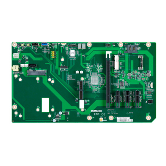
Introduction MIOe-DB5000 is MIOe evaluation board for MI/O-Compact and MI/O-Ultra SBC with standard ATX form factor. It’s compatible with MIOe, all circuit designs follow MI/O Extension design guide. MIOe-DB5000 have flexible interfaces for verification and various applications, including 1 display port, 3 PCIe, 1 mini PCIe, 1 SIM card holder, 1 USB 3.0, 1 USB 2.0, 1 LPC (Low Pin Count), 1 SMBus, 1 line out with amplifier, 1... -
Page 11: Placement
Generally, you simply need a standard cable to make most connections. Warning! To avoid damaging the computer, always turn off the power supply before setting jumpers. MIOe-DB5000 User Manual... -
Page 12: Jumper Table
Mini PCIE V1.2 Mini PCIe (2, 3) Mini PCIE V1.1 * Default Connector Table Table 1.2: Connector Table Connector Description MIOe PCIEx1 Slot (only MIOe-DB5000-00A1E) PCIEx1 Slot PCIEx1 Slot Mini PCIE Mini PCIE Holder SIM Card CPLD CN10 GPIO CN11... -
Page 13: Switch Table
Power Reset Jumper, Connector and Switch Pin Definition J1, J4, J5, J6 PH_3x1V_2.54mm Part Number 1653003100 Footprint HD_3x1P_100_D Description PIN HEADER 3x1P 2.54mm 180D(M) DIP 205-1x3GS Setting Function +V12SB_EXT +V12SB_DB5000 +V12SB_MIO Default is (1,2)- External 12V Power MIOe-DB5000 User Manual... - Page 14 +V3.3SB Default is (1-2), (3-4), (7-8), (9-10)- Mini PCIE V1.2 J3 PH_3x1V_2.00mm Part Number 1653003101 Footprint HD_3x1P_79_D Description PIN HEADER 3x1P 2.0mm 180D(M) DIP 2000-13 WS Setting Function +V3.3SB +V3.3_MINIPCIE +V3.3 Default is (2,3)- Mini PCIE V1.2 MIOe-DB5000 User Manual...
- Page 15 CN1 MIOe Part Number 1654004704 Footprint BB_40x2P_32_3150x235 Description Pin Name PCIE_RX0+ PCIE_TX0+ PCIE_RX0- PCIE_TX0- PCIE_RX1+ PCIE_TX1+ PCIE_RX1- PCIE_TX1- PCIE_RX2+ PCIE_TX2+ PCIE_RX2- PCIE_TX2- PCIE_RX3+ PCIE_TX3+ PCIE_RX3- PCIE_TX3- PCIE_CLK+ LOUTL PCIE_CLK- LOUTR AGND SMB_CLK SMB_DAT PCIE_WAKE# RESET# SLP_S3# CLK33M MIOe-DB5000 User Manual...
- Page 16 LPC_AD0 DDP_HPD LPC_AD1 LPC_AD2 DDP_AUX+ LPC_AD3 DDP_AUX- LPC_DRQ#0 LPC_SERIRQ DDP_D0+ LPC_FRAME# DDP_D0- USB0_D+ DDP_D1+ USB0_D- DDP_D1- USB1_D+/USB_SSTX+ DDP_D2+ USB1_D-/USB_SSTX- DDP_D2- USB2_D+/USB_SSRX+ DDP_D3+ USB2_D-/USB_SSRX- DDP_D3- USB_OC# +12VSB +12VSB MIOe-DB5000 User Manual...
- Page 17 MIOe-DB5000 User Manual...
- Page 18 CN2 PCIEx1 Slot Part Number 1654000394 Footprint PCISLOT-1X-KORTAK Description Pin Name +12V +12V JTAG2 JTAG3 JTAG5 +3.3V +3.3V PWRGD REFCLK+ REFCLK- HSIP0 HSIN0 +12V +12V +12V SMB_CLK SMB_DAT +3.3V JTAG1 +3.3VSB PCIE_WAKE# HSOP0 HSON0 MIOe-DB5000 User Manual...
- Page 19 CN3 PCIEx1 Slot Part Number 1654000394 Footprint PCISLOT-1X-KORTAK Description Pin Name +12V +12V JTAG2 JTAG3 JTAG5 +3.3V +3.3V PWRGD REFCLK+ REFCLK- HSIP0 HSIN0 +12V +12V +12V SMB_CLK SMB_DAT +3.3V JTAG1 +3.3VSB PCIE_WAKE# HSOP0 HSON0 MIOe-DB5000 User Manual...
- Page 20 PCIEx1 Slot Part Number 1654000394 Footprint PCISLOT-1X-KORTAK Description Pin Name +12V +12V JTAG2 JTAG3 JTAG5 +3.3V +3.3V PWRGD REFCLK+ REFCLK- HSIP0 HSIN0 +12V +12V +12V SMB_CLK SMB_DAT +3.3V JTAG1 +3.3VSB PCIE_WAKE# HSOP0 HSON0 MIOe-DB5000 User Manual...
- Page 21 CN5 Mini PCIE Part Number 1654002538 Footprint FOX_AS0B226-S68K7F Description MINI PCI E 52P 6.8mm 90D SMD AS0B226-S68N7H Pin Name WAKE# +3.3VSB +1.5V REFCLK- REFCLK+ PERST# PERn0 +3.3VSB PERp0 +1.5V SMB_CLK PETn0 SMB_DAT PETp0 USB D- USB D+ +3.3VSB +3.3VSB MIOe-DB5000 User Manual...
- Page 22 +1.5V +3.3VSB MIOe-DB5000 User Manual...
- Page 23 CN7 SIM Card Part Number 1654000639 Footprint SIM-WL608C Description SIM card conn 6p 90D(F)SMD WO/Pb WL608C3-M04-7F Pin Name +VUIM_PWR UIM_RESET UIM_CLK +VUIM_VPP UIM_DATA MIOe-DB5000 User Manual...
- Page 24 CN8 LPC Part Number 1653007220 Footprint HD_7x2P_79_F_D Description PIN HEADER 7*2P 180D(F) 2.0mm Pin Name +5VSB POWERGD LPC_SERIRQ LPC_DRQ#0 LPC_AD2 LPC_AD3 LPC_FRAME# LPC_AD0 MIO_RST# LPC_AD1 CLK33M_PCI0 MIOe-DB5000 User Manual...
- Page 25 CN9 CPLD Part Number 1653008102 Footprint HD_8x1P_100_D Description Pin Header 8*1P idiot- proof 180D pitch 2.54mm Pin Name +V3.3_JTAG CPLD_z_TDO CPLD_z_TDI ispEN# CPLD_z_TMS CPLD_z_TCK MIOe-DB5000 User Manual...
- Page 26 HD_5x2P_79_23N685B-10M10 Description BOX HEADER 5x2P 2.00mm 180D(M) SMD 23N685B-10M10 Pin Name +VDD_CN_GPIO GPIO0_D4 GPIO0_D0 GPIO0_D5 GPIO0_D1 GPIO0_D6 GPIO0_D2 GPIO0_D7 GPIO0_D3 CN11 SATA_7P Part Number 1654004659 Footprint SATA_7P_WATM-07DBN4A3B8UW_D Description Serial ATA Con 7p 180D(M)DIP 1.27mm WO/Pb(L=3.3) Pin Name MIOe-DB5000 User Manual...
- Page 27 CN12 SATA_22P Part Number 1654003098 Footprint WIN_WATB-22DL1PFU Description Pin Name +V3.3 +V3.3 +V3.3 RSVD +V12 +V12 +V12 SATA_TX+ SATA_TX- SATA_RX- SATA_RX+ MIOe-DB5000 User Manual...
- Page 28 CN14 SMBus (from MIOe) Part Number 1655904020 Footprint FPC4V-125M Description WAFER 4P 1.25mm 180D(M) SMD 85205-04001 Pin Name SMB_DAT SMB_CLK CN15 Reset Button Part Number 1655302020 Footprint WF_2P_79_BOX_R1_D Description WAFER BOX 2P 2.0mm 180D(M) DIP A2001WV2-2P Pin Name RESET_BUTTON MIOe-DB5000 User Manual...
- Page 29 Part Number 1655000077 Footprint ATXCON-2X12-42-1 Description ATX PWR CONN. 2x2P 4.2mm 180D(M) DIP 24W4310-04S Pin Name +V12SB_EXT +V12SB_EXT CN17 Display Port or HDMI * Part Number 1654003198 Footprint KORTAK_EE082C0S-HN3Z Description Pin Name +12V +12V +3.3V +3.3V PWRGD MIOe-DB5000 User Manual...
- Page 30 DDP_HPD DDP_AUX+ DDP_AUX- MIOe-DB5000 User Manual...
- Page 31 +12V +12V +12V +3.3V +3.3VSB DDP_D0+ DDP_D0- DDP_D1+ DDP_D1- DDP_D2+ DDP_D2- DDP_D3+ DDP_D3- MIOe-DB5000 User Manual...
- Page 32 * Depends on MI/O main board MIOe-DB5000 User Manual...
- Page 33 CN18 USB2.0 or USB3.0 * Part Number 1654009685 Footprint USB_9P_UEA0112C-4FH1-4F Description Pin Name SSRX- SSRX+ SSTX- SSTX+ * Depends on MI/O main board CN19 USB2.0 Part Number 1654005935 Footprint USB_4P_UB0112 Description Pin Name MIOe-DB5000 User Manual...
- Page 34 CN21, CN22 FAN_ W_3V_2.54mm Part Number 1655003010 Footprint WHP3VA Description Wafer 2.54mm 3P 180D(M) DIP W/LOCK 22-27-2031 Pin Name +V12 SW1 Power_WB_2V_2.00mm Part Number 1601000501 Footprint SW_4P_236x236_H197 Description PUSH SW STS-B5 SMD 4P H=5.0mm Pin Name POWER_BUTTON MIOe-DB5000 User Manual...
- Page 35 SW2 Reset_WB_2V_2.00mm Part Number 1601000501 Footprint SW_4P_236x236_H197 Description PUSH SW STS-B5 SMD 4P H=5.0mm Pin Name RESET_BUTTON MIOe-DB5000 User Manual...
- Page 36 No part of this publication may be reproduced in any form or by any means, electronic, photocopying, recording or otherwise, without prior written permis- sion of the publisher. All brand and product names are trademarks or registered trademarks of their respective companies. © Advantech Co., Ltd. 2012...