Table of Contents
Advertisement
Quick Links
Advertisement
Table of Contents

Related Manuals for Measurement Computing 6K-ERB08


Summary of Contents for Measurement Computing 6K-ERB08
- Page 2 6K-ERB08 8-relay accessory board for use with PCI-DAS6000 Series and PCI-DAC6700 Series boards User's Guide Document Revision 2, July, 2006 © Copyright 2006, Measurement Computing Corporation...
- Page 3 Measurement Computing. Thank you for choosing a Measurement Computing product—and congratulations! You own the finest, and you can now enjoy the protection of the most comprehensive warranties and unmatched phone tech support. It’s the embodiment of our two missions: To offer the highest-quality, computer-based data acquisition, control, and GPIB hardware and software available—at...
- Page 4 Information furnished by Measurement Computing Corporation is believed to be accurate and reliable. However, no responsibility is assumed by Measurement Computing Corporation neither for its use; nor for any infringements of patents or other rights of third parties, which may result from its use. No license is granted by implication or otherwise under any patent or copyrights of Measurement Computing Corporation.
-
Page 5: Table Of Contents
Introducing the 6K-ERB08........................ 1-1 Overview: 6K-ERB08 features........................1-1 Software features ............................1-1 Chapter 2 Installing the 6K-ERB08........................2-1 What comes with your 6K-ERB08 shipment?....................2-1 Hardware ..................................2-1 Additional documentation.............................. 2-2 Optional components ..............................2-2 Unpacking the 6K-ERB08..........................2-2 Connecting the 6K-ERB08 for I/O operations....................2-2 Connectors, cables –... - Page 6 6K-ERB08 User's Guide User connector P20................................ 4-3 User connector P21................................ 4-4 User connector P5................................4-5 User connector P6................................4-6...
-
Page 7: Preface
About this User’s Guide What you will learn from this user’s guide This user’s guide explains how to install, configure, and use the 6K-ERB08 so that you get the most out of its features. This user’s guide also refers you to related documents available on our web site, and to technical support resources. - Page 8 6K-ERB08 User's Guide About this User’s Guide Links to the hardware manuals for each board supported by the 6K-ERB08 are listed below: PCI-DAS6000 Series board Online User’s Guide PCI-DAS6013, PCI-DAS6014 www.mccdaq.com/PDFmanuals/pci-das6013-6014.pdf PCI-DAS6023, PCI-DAS6025 www.mccdaq.com/PDFmanuals/pci-das6025-23.pdf PCI-DAS6030, PCI-DAS6032 www.mccdaq.com/PDFmanuals/pci-das6030-32.pdf PCI-DAS6031, PCI-DAS6033 www.mccdaq.com/PDFmanuals/pci-das6031-33.pdf PCI-DAS6034, PCI-DAS6035, PCI-DAS6036 www.mccdaq.com/PDFmanuals/pci-das603x.pdf...
-
Page 9: Introducing The 6K-Erb08
This manual explains how to install and connect the 6K-ERB08 board with supported Measurement Computing hardware. You can use the 6K-ERB08 in your control applications to switch on and off a variety of devices, such as fans, blowers, pumps, etc. -
Page 10: Installing The 6K-Erb08
C-PCPOWER-10 cable — 10 foot cable that you can connect to your computer’s +5 V power supply connectors or to an external +5 V power supply. CB-PWR-9 AC adapter — 9 volt, 1 amp DC power supply, 110 VAC input. Six (6) standoffs with screws for attaching to the 6K-ERB08 board... -
Page 11: Additional Documentation
Follow the guidelines below when connecting the 6K-ERB08 to your computer and to your MCC hardware. Make sure your connections to the 6K-ERB08 do not exceed any of the specified maximum ratings, or you could damage the 6K-ERB08, your computer, and your 6000 Series control board. The maximum ratings for connections to the 6K-ERB08 are listed in Chapter 4 "Specifications... -
Page 12: Connectors, Cables - Interface I/O Connectors
Installing the 6K-ERB08 Connectors, cables – interface I/O connectors The 6K-ERB08 board’s eight relays are controlled by your 6000 Series control board’s digital channels through AUXPORT. Digital channels DIO<0:7> correspond to relays 1 to 8. Connect your signal cable from the 6000 Series control board’s interface connector to one of the interface connectors on the relay board. -
Page 13: Pin Out - Interface Connectors
6K-ERB08 User's Guide Installing the 6K-ERB08 Pin out – interface connectors Table 2-2. Connector P20 pin out Signal Name Signal Name • • • • P21 Pass Through 99 P21 Pass Through 49 P21 Pass Through 98 • • P21 Pass Through 48 •... - Page 14 6K-ERB08 User's Guide Installing the 6K-ERB08 Table 2-3. Connector P21 pin out Signal Name Signal Name • • P20 Pass Through 99 • • P20 Pass Through 49 P20 Pass Through 98 • • P20 Pass Through 48 P20 Pass Through 97 •...
- Page 15 6K-ERB08 User's Guide Installing the 6K-ERB08 Table 2-4. Connector P5 pin out Signal Name Signal Name • • P6 Pass Through 99 • • P6 Pass Through 98 P6 Pass Through 97 P6 Pass Through 96 • • P6 Pass Through 95 •...
-
Page 16: Signal Cables
6K-ERB08 User's Guide Installing the 6K-ERB08 Signal cables Figure 2-1. C100MMS-x cable Details on the C100MMS-x cable are available on our web site at www.mccdaq.com/cbicatalog/cbiproduct.asp?dept_id=104&pf_id=1514. Strain relief is stamped “Pins 1-50”. Pins 1-50 are on the long side of the “D” connector. -
Page 17: Connecting To Your 6000 Series Control Board
Connect one end of the cable to either 100-pin interface connector ( C100MMS-x on the 6K-ERB08, and connect the other end of the cable to the 100-pin interface connector on the 6000 Series control board. cable: Connect the 50-pin cable end stamped... -
Page 18: Power Source
AC adapter Figure 2-5. Power source jumper JP1configurations External +5 V PC power connections You can power the 6K-ERB08 with your computer’s +5 V power supply using the cord that C-PCPOWER-10 was shipped with the board. Each end of the cable has a keyed MOLEX type connector. To connect to your computer’s internal power connectors, do the following:... -
Page 19: Relay Logic
External +9V AC power adapter connections You can power the 6K-ERB08 using the AC power adapter (MCC part number CB-PWR-9). This adapter provides 9 volt, 1 amp DC power, 110 VAC power. To connect the AC adapter, do the following. -
Page 20: Functional Details
Chapter 3 Functional Details 6K-ERB08 block diagram 6K-ERB08 functions are illustrated in the block diagram shown here. regulator Screw terminal block Relay modules 1-4 Input power Channel 1 relay Channel 2 relay Relay control bits Relay driver DIO (0:3) Channel 3 relay... -
Page 21: Components
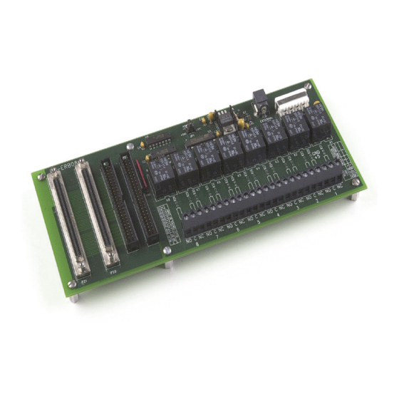
6K-ERB08 User's Guide Functional Details Components Major components on the 6K-ERB08 are shown in Figure 3-2 Figure 3-2. 6K-ERB08 component locations Table 3-8 describes the board’s major components. Table 3-8. 6K-ERB08 component descriptions Callout Board Description label P21, P20 100-pin interface connectors for connecting to the 6000 Series control board or different accessory boards. -
Page 22: Screw Terminal Connections
6K-ERB08 User's Guide Functional Details Screw terminal connections Connect external devices to the relay contacts using the 6K-ERB08 screw terminals. Each relay has a common (C), normally closed (NC), and normally open (NO) contact. Figure 3-3 shows the screw terminals on a typical relay channel. -
Page 23: Relay Contact Protection Circuit For Inductive Loads
6K-ERB08 User's Guide Functional Details Relay contact protection circuit for inductive loads When you connect an inductive load to a relay, energy stored in the inductive load can induce a large voltage surge when you switch the relay. This voltage can severely damage the relay contacts. To limit the voltage surge across the inductive load, install a kickback diode across the DC load. -
Page 24: 6K-Erb08 Assembly Diagram
6K-ERB08 User's Guide Functional Details 6K-ERB08 assembly diagram Figure 3-6. 6K-ERB08 assembly diagram... -
Page 25: Specifications
Chapter 4 Specifications Typical for 25 °C unless otherwise specified. Specifications in italic text are guaranteed by design. Power consumption Table 1. Power consumption specifications 5 V PC auxiliary power / PCI bus power / All relays off 15 mA typical, 20 mA max. external regulated All relays on 480 mA typical, 550 mA max. -
Page 26: Relay Screw Terminals
6K-ERB08 User's Guide Specifications Relay screw terminals Table 5. Relay screw terminal specifications Wire gauge range 12 AWG to 20 AWG Table 6. Screw terminal pin out Signal Name 1-NO Relay 1 Normally Open contact Relay 1 Common contact 1-NC... -
Page 27: Compatible Products
PCI-DAS6040 PCI-DAS6070 PCI-DAS6071 Analog output boards PCI-DAC6702 PCI-DAC6703 The 6K-ERB08 requires external power (for all products above) when used with C100HD50 Note 1: (pins 51-100) ribbon cable. Main connectors and pin out User connector P20 Table 11. Connector P20 specifications... -
Page 28: User Connector P21
6K-ERB08 User's Guide Specifications Signal name Signal name P21 Pass Through 29 P21 Pass Through 79 P21 Pass Through 30 P21 Pass Through 80 P21 Pass Through 31 P21 Pass Through 81 P21 Pass Through 32 P21 Pass Through 82... -
Page 29: User Connector P5
6K-ERB08 User's Guide Specifications Signal name Signal name P20 Pass Through 37 DIO2 P20 Pass Through 38 DIO3 PC +5V DIO4 P20 Pass Through 40 DIO5 P20 Pass Through 41 DIO6 P20 Pass Through 42 DIO7 P20 Pass Through 43... -
Page 30: User Connector P6
6K-ERB08 User's Guide Specifications User connector P6 Table 17. Connector P6 specifications Connector type Unshielded 50 pin ribbon connector - male Compatible cables C100HD50-x, C50FF-x, unshielded ribbon cable. x = 3 or 6 feet Table 18. P6 pin out Signal name... - Page 31 Address: 10 Commerce Way Suite 1008 Norton, MA 02766 Measurement Computing Corporation declares under sole responsibility that the product 6K-ERB08 to which this declaration relates is in conformity with the relevant provisions of the following standards or other documents: EU EMC Directive 89/336/EEC: Electromagnetic Compatibility, EN 61326 (1997) Amendment 1 (1998) Emissions: Group 1, Class A EN 55011 (1990)/CISPR 11: Radiated and Conducted emissions.
- Page 32 Measurement Computing Corporation 10 Commerce Way Suite 1008 Norton, Massachusetts 02766 (508) 946-5100 Fax: (508) 946-9500 E-mail: info@mccdaq.com www.mccdaq.com...
Need help?
Do you have a question about the 6K-ERB08 and is the answer not in the manual?
Questions and answers