Table of Contents
Advertisement
Quick Links
Advertisement
Table of Contents

Related Manuals for Measurement Computing CIO-DIO48H


Summary of Contents for Measurement Computing CIO-DIO48H
- Page 2 CIO-DIO48H Digital Input/Output Board User’s Guide Document Revision 1, December, 2006 © Copyright 2006, Measurement Computing Corporation...
- Page 3 Measurement Computing Corporation, nor its employees shall be liable for any direct or indirect, special, incidental or consequential damage arising from the use of its products, even if Measurement Computing Corporation has been notified in advance of the possibility of such damages. HM CIO-DIO48H.doc...
- Page 4 Trademark and Copyright Information TracerDAQ, Universal Library, Harsh Environment Warranty, Measurement Computing Corporation, and the Measurement Computing logo are either trademarks or registered trademarks of Measurement Computing Corporation. Windows, Microsoft, and Visual Studio are either trademarks or registered trademarks of Microsoft Corporation LabVIEW is a trademark of National Instruments.
-
Page 5: Table Of Contents
Introducing the CIO-DIO48H ...7 Overview: CIO-DIO48H features ...7 Software features ...7 Chapter 2 Installing the CIO-DIO48H ...8 What comes with your CIO-DIO48H shipment? ...8 Hardware ... 8 Additional documentation... 8 Optional components...8 Unpacking the CIO-DIO48H ...9 Installing the software ...9 Configuring the base address switch ...9... -
Page 6: Preface
What you will learn from this user's guide This user's guide explains how to install, configure, and use the CIO-DIO48H board so that you get the most out of its analog output features. This user's guide also refers you to related documents available on our web site, and to technical support resources. -
Page 7: Introducing The Cio-Dio48H
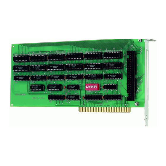
Introducing the CIO-DIO48H Overview: CIO-DIO48H features The CIO-DIO48H provides 48-bits of digital I/O. The I/O is organized into two 24-bit groups based on an 82C55 mode 0 emulation. Each 24-bit group is divided into three eight-bit ports labeled n is either "1" for FIRSTPORT or "2" for SECONDPORT. Port C can be split into two four-bit nibbles — Port C-HI and Port C-LO. -
Page 8: Installing The Cio-Dio48H
In addition to this hardware user's guide, you should also receive the Quick Start Guide (available in PDF at www.mccdaq.com/PDFmanuals/DAQ-Software-Quick-Start.pdf). This booklet supplies a brief description of the software you received with your CIO-DIO48H and information regarding installation of that software. Please read this booklet completely before installing any software or hardware. -
Page 9: Unpacking The Cio-Dio48H
The base address is the starting location that software writes to when communicating with the CIO-DIO48H. A set of DIP switches is used to set the base address. By placing the switch down, the CIO-DIO48H address decode logic is instructed to respond to that address bit. A complete address is constructed by calculating the HEX or decimal number which corresponds to all the address bits the board has been instructed to respond to. -
Page 10: Installing The Cio-Dio48H
PARALLEL PRINTER 2B0-2BF You can set the base address switch to any address in the range of 000-3F8. If you are not using IBM prototyping cards or another board which occupies these addresses, 300-31Fh are also free to use. Addresses not specifically listed, such as 390-39Fh, are not reserved and may be available. Check your computer for other boards which may use I/O addresses. -
Page 11: Connecting The Board For I/O Operations
Compatible cables Compatible accessory products with the C50FF-x cable Pinout – main I/O connector The CIO-DIO48H connector is a 50-pin male shrouded header connector that is accessible through the PC/AT expansion bracket. FIRSTPORTC Bit 0 FIRSTPORTC Bit 2 FIRSTPORTC Bit 4... -
Page 12: Cabling
IDC Connector Field wiring, signal termination, and conditioning You can use the following cabling, screw termination, and signal conditioning products with the CIO-DIO48H. CIO-TERM100 – 100-pin screw terminal board (daisy-chained 50-pin IDC connectors). Details on this product are available on our web site at www.mccdaq.com/cbicatalog/cbiproduct.asp?dept_id=102&pf_id=281. -
Page 13: Functional Details
Functional Details 82C55 emulation The CIO-DIO48H emulates the 82C55 chip. The 82C55 emulation initializes all ports as inputs on power-up and reset. A TTL input is a high impedance input. If you connect another TTL input device to the output, it could be turned on or off every time the board is reset. -
Page 14: Digital I/O Isolation
24-bits of digital I/O. You can configure the CIO-ERB24 relay output board and SSR-RACK24 I/O module rack in a daisy chain configuration to use all of the digital I/O bits provided by the CIO-DIO48H board. An example of the daisy chain configuration scheme for each board is shown on page 15. - Page 15 CIO-ERB24 SSR-RACK24 Figure 6. CIO-DIO48H to CIO-ERB24 or SSR-RACK24 daisy chain The 24 digital I/O bits on pins 25 to 48 (base address +0 through +2) control the first relay board. The 24 digital I/O bits on pins 1 to 24 control the second relay/SSR board on the daisy chain.
-
Page 16: Programming And Developing Applications
Only experienced programmers should try register-level programming. If you need to program at the register level in your application, refer to the Register Map for the CIO-DIO48, CIO-DIO48H, CIO-DIO96, and CIO-DIO192. This document is available on our website at http://www.mccdaq.com/registermaps/RegMapCIO-DIO-Series.pdf. -
Page 17: Specifications
Specifications Typical for 25 °C unless otherwise specified. Specifications in italic text are guaranteed by design. Digital input/output Digital type Configuration Number of channels Output high Output low Input high Input low Power-up / reset state Miscellaneous Power consumption Environmental Operating temperature range Storage temperature range Humidity... - Page 18 Signal name FIRSTPORTC Bit 0 FIRSTPORTC Bit 2 FIRSTPORTC Bit 4 FIRSTPORTC Bit 6 FIRSTPORTB Bit 0 FIRSTPORTB Bit 2 FIRSTPORTB Bit 4 FIRSTPORTB Bit 6 FIRSTPORTA Bit 0 FIRSTPORTA Bit 2 FIRSTPORTA Bit 4 FIRSTPORTA Bit 6 SECONDPORTC Bit 0 SECONDPORTC Bit 2 SECONDPORTC Bit 4 SECONDPORTC Bit 6...
-
Page 19: Declaration Of Conformity
Category: Electrical equipment for measurement, control and laboratory use. Measurement Computing Corporation declares under sole responsibility that the product CIO-DIO48H to which this declaration relates is in conformity with the relevant provisions of the following standards or other documents: EU EMC Directive 89/336/EEC: Electromagnetic Compatibility, EN55022 (1987), EN50082-1 Emissions: Group 1, Class B EN55022 (1987): Radiated and Conducted emissions. - Page 20 Measurement Computing Corporation 10 Commerce Way Suite 1008 Norton, Massachusetts 02766 (508) 946-5100 Fax: (508) 946-9500 E-mail: info@mccdaq.com www.mccdaq.com...
Need help?
Do you have a question about the CIO-DIO48H and is the answer not in the manual?
Questions and answers