Table of Contents
Advertisement
Quick Links
Advertisement
Table of Contents

Related Manuals for Measurement Computing PMD-1024HLS


Summary of Contents for Measurement Computing PMD-1024HLS
- Page 2 PMD-1024HLS Personal Measurement Device™ brand USB-based Digital I/O Module User's Guide Document Revision 4, May, 2005 © Copyright 2005, Measurement Computing Corporation™...
- Page 3 Your new Measurement Computing product comes with a fantastic extra — Management committed to your satisfaction! Refer to www.mccdaq.com/execteam.html for the names, titles, and contact information of each key executive at Measurement Computing. Thank you for choosing a Measurement Computing product—and congratulations! You own the finest, and you can now enjoy the protection of the most comprehensive warranties and unmatched phone tech support.
- Page 4 Trademark and Copyright Information Personal Measurement Device brand, TracerDAQ, Universal Library, InstaCal, Harsh Environment Warranty, Measurement Computing Corporation, and the Measurement Computing logo, are either trademarks or registered trademarks of Measurement Computing Corporation. SoftWIRE is a registered trademark of SoftWIRE Technology, Inc. Windows, Microsoft, and Visual Studio are either trademarks or registered trademarks of Microsoft Corporation.
-
Page 5: Table Of Contents
Table of Contents About this User's Guide........................v What you will learn from this user's guide ......................v Conventions in this user's guide..........................v Where to find more information .........................v Chapter 1 Introducing the PMD-1024HLS......................1-1 PMD-1024HLS block diagram ........................1-2 Software features ............................1-2 Connecting a PMD-1024HLS to your computer is easy................. -
Page 6: About This User's Guide
Preface About this User's Guide What you will learn from this user's guide This user's guide explains how to install, configure, and use the PMD-1024HLS so that you get the most out of its USB digital I/O features. This user's guide also refers you to related documents available on our web site, and to technical support resources that can also help you get the most out of your PMD-1024HLS. -
Page 7: Introducing The Pmd-1024Hls
Chapter 1 Introducing the PMD-1024HLS This user's guide contains all of the information you need to connect the PMD-1024HLS to your computer and to the signals you want to measure. The PMD-1024HLS is part of the Personal Measurement Device brand of USB-based data acquisition products. The PMD-1024HLS is a USB 2.0 low-speed module supported under Microsoft®... -
Page 8: Pmd-1024Hls Block Diagram
PMD-1024HLS User's Guide Introducing the PMD-1024HLS PMD-1024HLS block diagram PMD-1024HLS functions are illustrated in the block diagram shown here. USB 2.0 compliant interface 32-bit event counter Microcontroller 1 channel Port C Port C Discrete, low- Discrete, low- Port A Port B... -
Page 9: Connecting A Pmd-1024Hls To Your Computer Is Easy
PMD-1024HLS User's Guide Introducing the PMD-1024HLS Connecting a PMD-1024HLS to your computer is easy Installing a data acquisition device has never been easier. The PMD-1024HLS relies upon the Microsoft Human Interface Device (HID) class drivers. The HID class drivers ship with every copy of Windows that is designed to work with USB ports. We use the Microsoft HID because it is a standard, and its performance delivers full control and maximizes data transfer rates for your PMD-1024HLS. -
Page 10: Installing The Pmd-1024Hls
Chapter 2 Installing the PMD-1024HLS What comes with your PMD-1024HLS shipment? As you unpack your PMD-1024HLS, make sure that the following components are included. Hardware PMD-1024HLS USB cable (2 meter length) Software The Measurement Computing Data Acquisition Software CD contains the following software: InstaCal installation, calibration, and test utility TracerDAQ suite of virtual instruments SoftWIRE for VS .NET... -
Page 11: Documentation
PMD-1024HLS User's Guide Installing the PMD-1024HLS Documentation In addition to this hardware user's guide, you should also receive the DAQ Software Quick Start (available in PDF at www.mccdaq.com/PDFmanuals/DAQ-Software-Quick-Start.pdf). Read this booklet completely before installing any software and hardware. Unpacking the PMD-1024HLS As with any electronic device, you should take care while handling to avoid damage from static electricity. - Page 12 PMD-1024HLS User's Guide Installing the PMD-1024HLS When you connect the PMD-1024HLS for the first time, a popup balloon Found New Hardware (Windows XP) or dialog (other Windows versions) appear as the PMD-1024HLS is detected. Another balloon or dialog opens that identifies the PMD-1024HLS as a USB Found New Hardware Human Interface Device.
-
Page 13: Functional Details
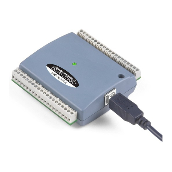
Chapter 3 Functional Details External components The PMD-1024HLS has the following external components, as shown in Figure 3-1. USB connector Screw terminal banks (2) Screw terminal pins 1 to 20 Screw terminal pins 21 to 40 connector/cable Figure 3-1. PMD-1024HLS external components USB connector The USB connector is on the right side of the PMD-1024HLS housing. -
Page 14: Screw Terminal Wiring
PMD-1024HLS User's Guide Functional Details Screw terminal wiring The PMD-1024HLS has two rows of screw terminals—one row on the top edge of the housing, and one row on the bottom edge. Each row has 20 connections. Pin numbers are identified here. -
Page 15: Digital I/O Terminals (Port A0 To A7, Port B0 To B7, Port C0 To C7)
PMD-1024HLS User's Guide Functional Details Digital I/O terminals (Port A0 to A7, Port B0 to B7, Port C0 to C7) Connect up to 24 digital I/O lines to the screw terminal containing pins 1 to 8 (Port C0 to Port C7), pins 21 to 28 (Port A0 to Port A7), and pins 32 to 39, (Port B0 to Port B7). -
Page 16: Power Terminals
PMD-1024HLS User's Guide Functional Details Port A0 +GND +5 V Figure 3-4. Schematic showing switch detection by digital channel Port A0 For more information on digital signal connections For more information on digital signal connections and digital I/O techniques, refer to the Guide to Signal Connections (available on our web site at www.mccdaq.com/signals/signals.pdf). -
Page 17: Ground Terminals
PMD-1024HLS User's Guide Functional Details If you want to sink the maximum of 64 mA per DIO line, you can only do so with up to six lines (440 mA ÷ 64 mA/line = 6.8 ≈ 6 lines). To sink current with all 24 DIO outputs at any one time, you can sink a maximum of 18 mA per line. - Page 18 PMD-1024HLS User's Guide Functional Details To configure a pull-down connection for a specific port, wire the pull-up/pull-down terminal to a GND terminal. Figure 3-6. Pull-down connection for Port A Wiring schematics are shown here for each pull-up/pull-down terminal. Dotted lines represent a pull- up or pull-down connection.
-
Page 19: Specifications
Chapter 4 Specifications Typical for 25 °C unless otherwise specified. Specifications in italic text are guaranteed by design. Digital input/output Table 4-1. Digital I/O specifications Digital input type 74ACT373 Digital output type 74FCT244 Number of I/O 24 (port A0 through port C7) Configuration 2 banks of 8 and 2 banks of 4 or 3 banks of 8... -
Page 20: Counter Section
PMD-1024HLS User's Guide Specifications Counter section Table 4-2. Counter specifications Pin name (Note 4) Counter type Event counter Number of channels Input source CTR screw terminal Resolution 32 bits Schmidt trigger hysteresis 20 mV to 100 mV Input leakage current ±1 µA... -
Page 21: General
PMD-1024HLS User's Guide Specifications General Table 4-4. General specifications Parameter Conditions Specification USB controller clock error 25 °C ±30 ppm max 0 to 70 °C ±50 ppm max Device type USB 1.1 low-speed Device compatibility USB 1.1, USB 2.0 Environmental Table 4-5. -
Page 22: Declaration Of Conformity
Declaration of Conformity Manufacturer: Measurement Computing Corporation Address: 16 Commerce Boulevard Middleboro, MA 02346 Category: Electrical equipment for measurement, control and laboratory use. Measurement Computing Corporation declares under sole responsibility that the product PMD-1024HLS to which this declaration relates is in conformity with the relevant provisions of the following standards or other documents: EU EMC Directive 89/336/EEC: Electromagnetic Compatibility, EN 61326 (1997) Amendment 1 (1998) - Page 23 Measurement Computing Corporation 16 Commerce Boulevard, Middleboro, Massachusetts 02346 (508) 946-5100 Fax: (508) 946-9500 E-mail: info@mccdaq.com www.mccdaq.com...
Need help?
Do you have a question about the PMD-1024HLS and is the answer not in the manual?
Questions and answers