
Related Manuals for Emerson VERDANT VX Series


Summary of Contents for Emerson VERDANT VX Series
- Page 1 PTAC Direct Sales, Inc. 185 S. Kimball Ave. Suite 130 Southlake, TX 76092 877.454.7822 (T) VX-TR-KT VX Series Wired Energy Management Thermostat with an Occupancy Sensor INSTALLATION MANUAL JULY 2021...
-
Page 2: Table Of Contents
Table of Contents Before You Begin ......................5 Equipment Nomenclature ..................5 Network Installation ....................6 Notice ......................6 Connecting the Antenna Module ..............7 Connecting the Ethernet Cable ............... 8 Powering the Server ..................9 Configuring the Online Connection Kit............10 Thermostat Installation ..................11 Mounting the Thermostat ................11 Occupancy Sensor Installation (Optional) ...............12 Mounting an Occupancy Sensor ..............12... - Page 3 Table of Contents 09 – NIGHT OCCUPANCY END ................32 10 – TEMPERATURE RECOVERY TIME ..............33 11 – RECOVERY TEMPERATURE - HEAT..............34 12 – TEMPERATURE SETBACK DELAY - HEAT ............35 13 – MINIMUM SETBACK TEMPERATURE ..............36 14 –...
- Page 4 Introduction Verdant VX Series Energy Management Thermostats deliver unprecedented energy savings without compromising the comfort of occupants. An integrated occupancy sensor uses a combination of motion and thermal sensing technologies for accurate occupancy detection. Reliable occupancy detection allows for energy savings when rooms are unoccupied.
-
Page 5: Before You Begin
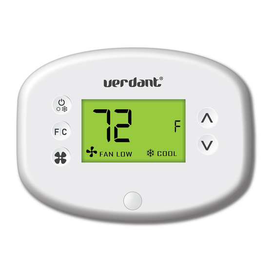
Before You Begin Equipment Nomenclature Before you begin installing Verdant equipment, we recommend familiarizing yourself with the various components that may be included in your shipment. VX Thermostat HVAC Controller Occupancy Sensor Online Connection Kit (Optional) (Optional) -
Page 6: Network Installation
Network Installation NOTICE TO ENABLE NETWORKING CAPABILITIES OF THE VX THERMOSTAT, REFER TO THE “NETWORK INSTALLATION” SECTION OF THIS MANUAL. BEFORE STARTING THE INSTALLATION OF THE NETWORKED THERMOSTATS, ENSURE THAT THE ONLINE CONNECTION KIT IS CONNECTED TO THE INTERNET. THE ONLINE CONNECTION KIT MUST BE PLUGGED INTO AN INTERNET PORT WITH A STATIC IP ADDRESS WITH DHCP ACTIVE. -
Page 7: Connecting The Antenna Module
Network Installation Connecting the Antenna Module Screw the Antenna onto the Wireless Receiver; ➤ Connect the Wireless Receiver to the Server using the supplied USB cable; ➤ Affix the Wireless Receiver to the wall with double sided adhesive tape (not ➤... -
Page 8: Connecting The Ethernet Cable
Network Installation Connecting the Ethernet Cable Connect the Server to the LAN port with the supplied RJ-45 cable. ➤... -
Page 9: Powering The Server
Network Installation Powering on the Server Plug the Server into an electrical outlet with the supplied power cord. ➤ TO PREVENT POWER RELATED ISSUES, PLUG THE SERVER INTO A UPS (UNINTERRUPTED POWER SUPPLY) UNIT. -
Page 10: Configuring The Online Connection Kit
Network Installation Configuring the Online Connection Kit Ensure the Online Connection Kit is receiving a Static IP address via DHCP ➤ Server. A public IP will not work; Ensure that the MAC address is properly Whitelisted if it needs to bypass ➤... -
Page 11: Thermostat Installation
Thermostat Installation Mounting the Thermostat to the Wall Select the appropriate installation location for the thermostat, taking into ➤ account the following; THE THERMOSTAT’S OCCUPANCY SENSOR SHOULD FACE THE BED AREA OF THE ROOM OR THE AREA WHERE THE OCCUPANT WILL SPEND THE MOST TIME. -
Page 12: Occupancy Sensor Installation (Optional)
Occupancy Sensor Installation Mounting the Occupancy Sensor (Optional) Select the appropriate installation location for the external occupancy sensor, ➤ taking into account the following; THE OCCUPANCY SENSOR SHOULD FACE THE DESIRED OCCUPANCY DETECTION AREA. With the faceplate removed, place the sensor on the wall in the installation ➤... -
Page 13: Installing A Wireless Occupancy Sensor
Occupancy Sensor Installation Installing the Wireless Sensor Receiver (Optional - Wireless Sensors Only) Plug the Sensor Receiver and plug it into the thermostat; ➤ With the faceplate removed, place the sensor on the wall in the installation ➤ location and mark location for drilling holes for the two (2) mounting screws; Drill two (2) 3/16”... -
Page 14: Installing A Wired Occupancy Sensor
Occupancy Sensor Wiring Wiring the Occupancy Sensor (Optional - Wired Sensors Only) Fish the wire from the back of the occupancy sensor to the thermostat ➤ location. Connect the wiring from the sensor to the wire harness already plugged into ➤... -
Page 15: Thermostat Configuraton
Thermostat Configuration Configuring the Thermostat With the thermostat and HVAC unit powered, follow the configuration instructions to correctly configure the thermostat. To ensure proper operation of the HVAC unit, complete the following steps. Enter the room number; ➤ Enter the equipment code; ➤... -
Page 16: Accessing The Configuration Screen
Thermostat Confi guration Accessing the Confi guration Screen Ensure the thermostat is powered and faceplate removed; ➤ Press the confi g button; ➤ CONFIGURATION BUTTON NOTE: You can access Thermostat Configuration settings at any time by pressing the “Configuration” button. The thermostat confi guration screens have a 30-second time-out. -
Page 17: Entering The Room Number
Thermostat Confi guration Entering the Room Number Enter the room number by changing the digits on the screen. Leading zeros “0” preceding other digits will be ignored, i.e. Room number “123” should be entered as “00123”. Press the FAN button to advance to the next digit; ➤... -
Page 18: Configuring The Equipment Type
Thermostat Confi guration Confi guring the Equipment Settings Enter the equipment code by changing the digits on the screen. Use the table below to determine the correct equipment codes based on your specifi c HVAC unit. Press the FAN button to advance to the next equipment setting. ➤... -
Page 19: Configuring Energy Savings Settings
Thermostat Confi guration Confi guring the Energy Saving Settings Press the UP and DOWN buttons to increase or decrease the energy savings ➤ preset. Press the F|C button to advance to the next menu. ➤ Preset Energy Savings Presets E-0* Energy Savings Off - No Temperature Setback Lowest Energy Savings Lower Energy Savings... -
Page 20: Setting The Thermostat Clock
Thermostat Confi guration Setting the thermostat clock HOURS MINUTES Set the thermostat clock to current time in 24h (Military Time) format. Press the FAN button to advance to the next digit; ➤ Press the UP and DOWN buttons to increase or decrease the digits ➤... -
Page 21: Testing The Thermostats
Thermostat Configuration Testing the Thermostat Following the thermostat configuration, test if the thermostat is controlling the HVAC unit. Ensure the thermostat is powered and the faceplate is on. ➤ Press the DOWN button to change the temperature set point below the ➤... -
Page 22: Custom Energy Savings Settings
Custom Energy Savings Settings If you don’t want to use the one of the energy saving presets listed on page 17 and detailed in the Appendix 1, you can enter the custom energy savings settings. Accessing the Thermostat Settings Press and hold the “Confi guration” button until the fi rst thermostat settings ➤... -
Page 23: Using The Thermostat Settings Screens
Custom Energy Savings Settings Using the Thermostat Settings Screens SETTING VALUE SCREEN NUMBER Use the “Up” and “Down” buttons to change the setting; ➤ Press the “F/C” button to advance to the next setting; ➤ Press the “Fan” button to return to the previous setting; ➤... -
Page 24: Fan Control Mode
Custom Energy Savings Settings 01 – FAN CONTROL MODE Select Fan Control Mode: MANUAL - guest can select automatic or continuous fan mode; 01 * AUTOMATIC - fan runs only when there is a demand for heating or air conditioning; Indicates default setting;... -
Page 25: St Stage Differential - Heat
Custom Energy Savings Settings 02 – 1 STAGE DIFFERENTIAL - HEAT 02-30 (0.2°F - 3.0°F; 0.5°F* default setting) Select the number of degrees the thermostat has to sense between the automatic changeover temperature for heat and the room temperature before a call for the 1st stage heating is initiated. -
Page 26: Nd Stage Differential - Heat
Custom Energy Savings Settings 03 – 2 STAGE DIFFERENTIAL - HEAT 10-20 (1.0°F - 2.0°F*; 2.0°F* default setting) Select the difference between 1st stage heating and 2nd stage heating initiation. -
Page 27: 1St Stage Differential - Cool
Custom Energy Savings Settings 04 – 1ST STAGE DIFFERENTIAL - COOL 02-30 (0.2°F - 3.0°F; 0.5°F* default setting) Select the number of degrees the thermostat has to sense between the automatic changeover temperature for cool and the room temperature before a call for the 1st stage cooling is initiated. -
Page 28: Incidental Occupancy Threshold
Custom Energy Savings Settings 05 – INCIDENTAL OCCUPANCY THRESHOLD 00-60 (05* default setting) Select the minimum period of time (in minutes) for which occupancy needs to be detected to enter the guest occupancy mode. When occupancy is detected, thermostat will switch to occupied mode for a duration of “Incidental Occupancy Threshold”... -
Page 29: Night Occupancy Threshold
Custom Energy Savings Settings 06 – NIGHT OCCUPANCY THRESHOLD 00-60 (01* default setting) Select the minimum period of time (in minutes) for which occupancy needs to be detected in order to consider the room occupied during the “Night Occupancy”period. When occupancy is detected during the “Night Occupancy Period” for longer than the “Night Occupancy Threshold”... -
Page 30: Forced 2Nd Stage Heating
Custom Energy Savings Settings 07 – FORCED 2ND STAGE HEATING 00-60 (30* default setting) Select a number of minutes 1st stage heating will run before 2nd stage heating is automatically initiated if the guest set point is not reached and the 2nd stage heating is not initiated through differential settings. -
Page 31: Night Occupancy Start
Custom Energy Savings Settings 08 – NIGHT OCCUPANCY START 00-23 (21* default setting) Select the start time (in hours - 24-hour clock) for “Night Occupancy” If occupancy is detected for a period of time longer than the “Night Occupancy Threshold” during “Night Occupancy” period, the thermostat will disable the occupancy sensor and consider the room occupied until the end of the “Night Occupancy”... -
Page 32: Night Occupancy End
Custom Energy Savings Settings 09 – NIGHT OCCUPANCY END 00-23 (09* default setting) Select the time (in hours - 24-hour clock) for “Night Occupancy” to end. The time of day the “Night Occupancy” ends and the thermostat switches back to the room sensing settings chosen in the other occupancy modes. -
Page 33: Temperature Recovery Time
Custom Energy Savings Settings 10 – TEMPERATURE RECOVERY TIME 00-60 (25* default setting) Select the maximum time allowed for a PTAC unit to attain temperature as defi ned by Heat and Cool “Recovery Temperature”; “Temperature Recovery Time” selected here and the actual temperature recovery ability of the PTAC unit are used to calculate setback temperatures. -
Page 34: Recovery Temperature - Heat
Custom Energy Savings Settings 11 – RECOVERY TEMPERATURE - HEAT 62-82 (67°F* default setting) Select the room temperature in °F that a PTAC unit will have to attain within the selected “Temperature Recovery Time” when there is a need for heating. -
Page 35: Temperature Setback Delay - Heat
Custom Energy Savings Settings 12 – TEMPERATURE SETBACK DELAY - HEAT 00-120 (20* default setting) Select the time delay (in minutes) for which the room that is in the guest occupancy mode needs to be unoccupied before the temperature setback is initiated. This feature prevents initiating temperature setback prematurely while the guest is still in the room but in an area where occupancy cannot be detected by the occupancy sensor. -
Page 36: Minimum Setback Temperature
Custom Energy Savings Settings 13 – MINIMUM SETBACK TEMPERATURE 52-72 (64°F* default setting) Select the “Minimum Setback Temperature” in °F. Setback temperature is calculated by measuring PTAC unit’s ability to attain “Recovery Temperature - Heat” within “Temperature Recovery Time”. If recovery is disabled (“Temperature Recovery Time” is set to “0”) or if setback temperatures have not yet been calculated, the “Minimum Setback Temperature”... -
Page 37: Temperature Setback Delay - Cool
Custom Energy Savings Settings 14 – TEMPERATURE SETBACK DELAY - COOL 00-120 (20* default setting) Select the time delay (in minutes) for which the room that is in the guest occupancy mode needs to be unoccupied before the temperature setback is initiated. This feature prevents initiating temperature setback prematurely while the guest is still in the room but in an area where occupancy cannot be detected by the occupancy sensor. -
Page 38: Maximum Setback Temperature
Custom Energy Savings Settings 15 – MAXIMUM SETBACK TEMPERATURE 72-92 (78°F* default setting) Select the “Maximum Setback Temperature” in °F. Setback temperature is calculated by measuring PTAC unit’s ability to attain “Recovery Temperature - Cool” within “Temperature Recovery Time”. If recovery is disabled (“Temperature Recovery Time” is set to “0”) or if setback temperatures have not yet been calculated, the “Maximum Setback Temperature”... -
Page 39: Recovery Temperature - Cool
Custom Energy Savings Settings 16 – RECOVERY TEMPERATURE - COOL 62-82 (74°F* default setting) Select the room temperature in °F that a PTAC unit will have to attain within the selected “Temperature Recovery Time” when there is a need for air conditioning. -
Page 40: Minimum Set Point
Custom Energy Savings Settings 17 – MINIMUM SET POINT 64-84 (66°F* default setting) Select the minimum set point in °F that a guest can select. -
Page 41: Maximum Set Point
Custom Energy Savings Settings 18 – MAXIMUM SET POINT 60-82 (78°F* default setting) Select the maximum set point in °F that a guest can select. -
Page 42: Temperature Control Mode
Custom Energy Savings Settings 19 – TEMPERATURE CONTROL MODE Select Temperature Control Mode: MANUAL - Allows users to select HEAT only or COOL only temperature control mode to maintain the room temperature; 01 * AUTOMATIC - Thermostat automatically turns on heating or air conditioning to maintain the room temperature at the selected temperature set point;... -
Page 43: Auto Changeover Set Point Offset (Dead Band)
Custom Energy Savings Settings 20 – AUTO CHANGEOVER SET POINT OFFSET 00-04 (01°F* default setting) Select the difference between the guest-selected set point and the heat and the cool set point when the thermostat is in the automatic temperature control mode. This value plus the 1st stage differential defi ned in steps 02 and 04, defi nes the temperature at which the thermostat would automatically change heating/cooling modes. -
Page 44: Setback Set Points / Auto-Restore
Custom Energy Savings Settings 21 – SETBACK SET POINTS / AUTO-RESTORE When room is unoccupied and the thermostat is in the setback mode or turned off, it will NOT maintain the temperature between heat and cool setback set points; When guest enters the room, the thermostat will be turned off - it will not automatically restore the most recent guest settings;... -
Page 45: Auto Changeover Set Point Offset (Dead Band)
Custom Energy Savings Settings 22 – AUTOMATIC HUMIDITY CONTROL † Disable automatic humidity control; 01 * Enable automatic humidity control; When “Automatic Humidity Control” is enabled, thermostat will turn on air conditioning in an unoccupied room when humidity raises above 60% and room temperature is above 72°F until either room humidity is below 55% or room temperature is below 72°F;... -
Page 46: 23 -Temperature Calibration
Custom Energy Savings Settings 23 – TEMPERATURE CALIBRATION -5.0 – 5.0 (0.0°F* default setting) Calibrate the temperature display : -5.0°F - 5.0°F. -
Page 47: Occupancy Sensor Configuration
Confi guring & Managing Accessories Accessing the Sensor Confi guration Screen With the thermostat and HVAC unit powered, follow the sensor confi guration instructions to correctly confi gure the sensor. Remove the faceplate from the thermostat ➤ Press and hold the CONFIG button until 0011 appears on the screen. ➤... -
Page 48: Configuring The Occupancy Sensor
Confi guring & Managing Accessories Confi guring a Wired Sensor Press the CONFIG button once. The screen will show CCC. ➤ Press the F|C button four (4) times or until you arrive at a screen that shows J0 ➤ Press the UP button on the thermostat to make sure the screen reads J1 ➤... -
Page 49: Changing The Sensor Configuration
Configuring & Managing Accessories Changing the Sensor Configuration between Normally Open & Normally Closed To change the Lighting signal between Normally Open or Normally closed: Turn thermostat ON; ➤ Press & hold the CONFIG button for 5 seconds, the screen will show 0011; ➤... -
Page 50: Troubleshooting
Troubleshooting Error Codes ERR 1 Thermostat Temperature Sensor Hardware Defect ERR 2 Thermostat Radio Hardware Defect ERR 3 Thermostat Radio Software Defect ERR 5 Thermostat Memory Defect... -
Page 51: Pairing The Thermostat With A Network Programmer
Troubleshooting Pairing the thermostat In the case of a networked installation with online management, the thermostat must be paired with a Network Programmer specific to the property before the installation. The thermostat must not be powered during the pairing procedure. Plug the HDMI cable into the mini HDMI port on the thermostat;... -
Page 52: Restoring Factory Settings
Troubleshooting Restoring Factory Settings If there are reported errors or configuration issues, the user may restore factory settings to return the thermostat to its default parameters. Procedure Remove the faceplate of the thermostat; ➤ With the thermostat on, press the CONFIG button located on the control ➤... -
Page 54: Appendix 1 - Energy Saving Presets
APPENDIX 1 - Energy Saving Presets Level Level Level Level Level Level Fan Control Mode AUTO AUTO AUTO AUTO AUTO AUTO 1st Stage Differential Heat 2nd Stage Differential Heat 1st Stage Differential Cool Guest Occupancy Threshold Night Occupancy Threshold Force 2nd Stage Heating After Night Occupancy Start Night Occupancy End Recovery Time... -
Page 55: Appendix 2 - Glossary
APPENDIX 2 - Glossary “Automatic Fan Control Mode” - fan runs only when there of time (in minutes) for which occupancy needs to be is a demand for heating or cooling; detected in order to enter the “Guest Occupancy” mode; “Manual Fan Control Mode”... - Page 56 Warranty Information For details on Verdant’s warranty policy, please visit www.verdant.co/verdant-warranty.
- Page 59 THIS DEVICE COMPLIES WITH PART 15 OF THE FCC RULES. OPERATION IS SUBJECT TO THE FOLLOWING TWO CONDITIONS: (1) THIS DEVICE MAY NOT CAUSE HARMFUL INTERFERENCE, AND (2) THIS DEVICE MUST ACCEPT ANY INTERFERENCE RECEIVED, INCLUDING INTERFERENCE THAT MAY CAUSE UNDESIRED OPERATION. THE MANUFACTURER IS NOT RESPONSIBLE FOR ANY RADIO OR TV INTERFERENCE CAUSED BY UNAUTHORIZED MODIFICATIONS TO THIS EQUIPMENT.
-
Page 60: Technical Specifications
Technical Specifications Thermostat Case Dimensions (Imperial) 4.02 x 5.51” x 0.93” Case Dimensions (Metric) 102mm x 140mm x 23.5mm Screen Dimensions (Imperial) 3.63” x 2.13” Screen Dimensions (Metric) 92mm x 54mm Operating Voltage 24VAC Fan High (GH) Fan Low (GL) Compressor (Y) Control Outputs Heat Pump (OB)
Need help?
Do you have a question about the VERDANT VX Series and is the answer not in the manual?
Questions and answers