Table of Contents
Advertisement
Available languages
Available languages
Optional Accessory: Wall Cover-Up Plate F61-2663, 6-3/4" W x 4-1/2" H
INDEX
Thermostat Installation
2-4
Wiring
2
Installer Menu
3-4
Test Equipment
4
Using the Thermostat
5-7
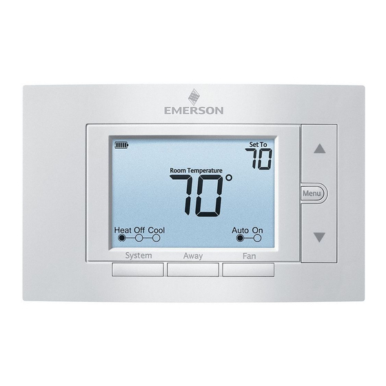
Thermostat Overview
5
User Menu
6
Thermostat Operation
6
Troubleshooting
7-8
Homeowner Help Line
8
SPECIFICATIONS
Electrical Rating:
Battery Power ..................................... mV to 30 VAC, NEC Class II, 50/60 Hz
Input-Hardwire .................................... 20 to 30 VAC, NEC Class II, 50/60 Hz
Terminal Load .......................................... 1.5 A per terminal, 2.5A maximum all terminals combined
Setpoint Range ........................................ 45° to 99° F (7° to 37° C)
Rated Differentials (@ 6°F/ Hr):
Fast
Heat (Conventional Gas / Oil / Elect) ..... 0.5°F
Cool (Central Air) ................................. 0.9°F
Heat Pump (Heat and Cool) ................ 0.9°F
Heat Pump Aux. .................................. 0.5°F
Operating Ambient .................................. 32°F to +105°F (0° to +41°C)
Display Temperature Range ....................... 32°F to +99°F (0 to 37°C)
Operating Humidity ................................. 90% non-condensing maximum
Shipping Temperature Range ................... -20°F to + 150°F (-29° to +65°C)
Thermostat Dimensions ........................... 3-3/4" H x 6" W x 1-1/8" D
white-rodgers.com
emersonclimate.com
1F85U-42NP (Non-Programmable)
Installation and Operating Instructions
80 Series
Universal Thermostat
TM
Battery Powered or Hardwired with Common
Maximum
Thermostat Applications
Stages
Heat/ Cool
Conventional Gas, Oil, Electric
(mV and 24V), Heat only, Cool only or
Heat/Cool Systems
Heat Pump (Air Source or Geothermal)
with Aux. Heat
MERCURY NOTICE: This product does not contain
mercury. However, this product may replace a product
that contains mercury. Mercury and products containing
mercury must not be discarded in household trash.
Refer to www.thermostat-recycle.org for information
on disposing of products containing mercury.
Med
Slow
0.75°F
1.9°F
1.2°F
1.7°F
1.2°F
1.7°F
0.75°F
1.9°F
PART NO. 37-7573B-EN
WIRING
Refer to equipment manufacturer's instructions for specific system wiring information. After wiring, see
INSTALLER MENU for proper thermostat configuration. Wiring table shown are for typical systems and
describe the thermostat terminal functions. Wiring will change when dedicated emergency heat is on
(See Installer menu #15).
Terminal Designations
6 (not shown) - 3 wire zone valve
2/2
4/2
Precautions
• Do not exceed the specification ratings.
• All wiring must conform to local and national electrical codes and ordinances.
• This control is a precision instrument, and should be handled carefully. Rough handing or
distorting components could cause the control to malfunction.
Do not use on circuits exceeding specified voltage.
Higher voltage will damage control and could
Do not short out terminals on gas valve or primary
control to test. Short or incorrect wiring will burn
out thermostat and could cause personal injury
1535
THERMOSTAT INSTALLATION
RC
Power (24V) - Cooling
RH
Power (24V) - Heating
Reversing Valve or output for 3 wire zone valves
O/B
Configurable as "O" or "B" Reversing Valve or 3 wire
zone heat (power close)
1st Stage Compressor
Y
G
Fan Relay
1st Stage Heat (conventional);
1st Stage Auxiliary Heat (heat pump)
W/E
Can operate as Emergency Heat only
(See Installer Menu #15)
Common wire for 24V (optional with batteries)
C
Heat Pump Malfunction / Diagnostic terminal
L
(input signal requires common)
Y2
2nd Stage compressor
2nd Stage Heat (Conventional)
2nd Stage Auxiliary Heat (Heat Pump)
W2
Can operate as 1st Stage Auxiliary Heat
(See Installer Menu #15)
WARNING
!
To prevent electrical shock and/or equipment
damage, disconnect electrical power to system,
cause shock or fire hazard.
at main fuse or circuit breaker box,until
and/or property damage.
CAUTION
!
To prevent compressor and/or property damage, if the outdoor temperature is below 50°F,
DO NOT operate the cooling system.
Do not allow the compressor to run unless the compressor oil heaters have been operational
for 6 hours and the system has not been operational for at least 5 minutes.
Terminal Function
Leveling Thermostat
Leveling is for appearance only and
will not affect thermostat operation.
CAUTION
!
installation is complete.
2
Advertisement
Table of Contents

Subscribe to Our Youtube Channel
Related Manuals for Emerson 1F85U-42NP


Summary of Contents for Emerson 1F85U-42NP
-
Page 1: Wiring
1F85U-42NP (Non-Programmable) THERMOSTAT INSTALLATION Installation and Operating Instructions WIRING 80 Series Universal Thermostat Battery Powered or Hardwired with Common Refer to equipment manufacturer’s instructions for specific system wiring information. After wiring, see INSTALLER MENU for proper thermostat configuration. Wiring table shown are for typical systems and describe the thermostat terminal functions. -
Page 2: Installer Menu
INSTALLER MENU (C0ntinued) RC/RH Jumper Wire This thermostat electrically connects Settings Installer’s Menu # Default Setting Description the RC and RH terminals so a jumper (flashing icons) (Hold Menu 8 Seconds) (Press wire is not required. If the application °F – Fahrenheit Fahrenheit or Celsius °F °C –... -
Page 3: User Menu
USER MENU USING THE THERMOSTAT To customize thermostat settings, press the Menu button from the home screen. Use the buttons to highlight Settings and press Next. Use Next and Back to navigate THERMOSTAT OVERVIEW through menu items. Press to change the setting. Before you begin using your thermostat, you should be familiar with its features, display and User’s Menu # the location/operation of the thermostat buttons and switches. -
Page 4: Troubleshooting
35) If an acceptable cycle rate is not achieved, HOMEOWNER HELP LINE: 1-800-284-2925 contact your HVAC service person. (Troubleshooting continued on next page) White-Rodgers is a business of Emerson Electric Co. The Emerson logo is a trademark and service mark www.white-rodgers.com of Emerson Electric Co. www.emersonclimate.com... -
Page 5: Installation Du Thermostat
1F85U-42NP (non programmable) INSTALLATION DU THERMOSTAT Instructions d’installation et d’utilisation CÂBLAGE Thermostat universel série 80 Alimentation par piles ou câblée avec fil commun Consultez le mode d’emploi du fabricant de l’appareil pour les informations spécifiques au câblage du système. Après le câblage, consultez la section MENU DE L’INSTALLATEUR pour configurer correctement le thermostat. - Page 6 MENU DE L’INSTALLATEUR (suite) Cavalier RC/RH Ce thermostat connecte électriquement Num. de menu Réglage par Réglages les bornes RC et RH de façon que cette Description d’installateur défaut opération ne soit pas nécessaire avec un (appuyez sur (enfoncez Menu 8 secondes) (icônes clignotantes) cavalier.
-
Page 7: Utilisation Du Thermostat
MENU DE L’UTILISATEUR UTILISATION DU THERMOSTAT Pour personnaliser les réglages du thermostat, appuyez sur le bouton Menu à partir de l’écran d’accueil. Utilisez les boutons pour sélectionner Settings (Réglages) puis appuyez sur Next (Suivant). Utilisez Next (Suivant) et Back (Précédent) pour naviguer dans les articles du menu. APERÇU DU THERMOSTAT Appuyez sur pour modifier le réglage. -
Page 8: Dépannage
LIGNE D’ASSISTANCE POUR LES PROPRIÉTAIRES : 1-800-284-2925 restreinte) local pour des suggestions supplémentaires. (suite du dépannage à la page suivante) White-Rodgers est une entreprise d’Emerson Electric Co. Le logo d’Emerson est une marque de commerce et une marque de www.white-rodgers.com service d’Emerson Electric Co. www.emersonclimate.com... -
Page 9: Instalación Del Termostato
1F85U-22PR (Programable) INSTALACIÓN DEL TERMOSTATO Instrucciones de instalación y operación CONEXIONES Termostato Universal Serie 80 Alimentación por pilas o conexión por cable con Consulte las instrucciones del fabricante del equipo para obtener información específica de las conexiones. Una neutro vez realizadas las conexiones eléctricas, consulte el MENÚ DE INSTALACIÓN para ver las instrucciones para la configuración adecuada del termostato. -
Page 10: Menú De Instalación
MENÚ DE INSTALACIÓN (continuación) RC/RH Cable puente Este termostato conecta eléctricamente Configuración Menú de instalación N° Opciones las terminales RC y RH por lo que no es Descripción predeterminada (Mantenga presionado Menu (Presione durante 8 segundos) necesario un cable puente. Si la aplicación (iconos intermitentes) 7 –... -
Page 11: Cómo Usar El Termostato
MENÚ DEL USUARIO Nota: Si aparece en la pantalla Starting Soon (comenzará pronto), la característica de bloqueo del compresor está funcionando. Habrá un retraso de hasta 5 minutos antes de que el compresor se Para personalizar las opciones del termostato, presione el botón Menu desde la pantalla de inicio. encienda (ver MENÚ... -
Page 12: Solución De Problemas
Emerson Electric Co. calefacción esté funcionando correctamente. (La Solución de problemas continúa en la página siguiente) El logotipo de Emerson es una marca comercial y una marca de www.white-rodgers.com servicio de Emerson Electric Co.
Need help?
Do you have a question about the 1F85U-42NP and is the answer not in the manual?
Questions and answers