Advertisement
Optional Accessory: Wall Cover-up Plate F61-2663, 6 3/4" W x 4 1/2" H
INDEX
Thermostat Installation
2-4
Wiring
2
3-4
Installer Menu
Using the Thermostat
5-6
Thermostat Overview
5
User Menu
6
Troubleshooting
7-8
8
Homeowner Help Line
SPECIFICATIONS
Electrical Rating:
Battery Power ..................................... 20 to 30 VAC, NEC Class II, 50/60 Hz
Input-Hardwire .................................... 20 to 30 VAC, NEC Class II, 50/60 Hz
Terminal Load .......................................... 1.5 A per terminal, 2.5A maximum all terminals combined
Setpoint Range ........................................ 45° to 99° F (7° to 37° C)
Rated Differentials (@ 6°F/ Hr):
Fast
Heat Pump (Heat)................................ 0.9°F
Heat Pump (Cool) ................................ 0.9°F
Auxiliary Heat ...................................... 0.5°F
Operating Ambient .................................. 32°F to +105°F (0° to +41°C)
Display Temperature Range ....................... 32°F to +99°F (0 to 37°C)
Operating Humidity ................................. 90% non-condensing maximum
Shipping Temperature Range ................... -20°F to + 150°F (-29° to +65°C)
Thermostat Dimensions ........................... 3-3/4" H x 6" W x 1-1/8" D
emersonthermostats.com
white-rodgers.com
1F83H-21NP (Non-Programmable)
Installation and Operating Instructions
80 Series Heat Pump Thermostat
Battery Powered or Hardwired with Common
Maximum
Thermostat Applications
Stages
Heat /Cool
Single Stage Compressor, Heat Pump
Systems (air source or geothermal) –
1 Stage Aux/Emergency Heat
MERCURY NOTICE: This product does not contain
mercury. However, this product may replace a product
that contains mercury. Mercury and products containing
mercury must not be discarded in household trash.
Refer to www.thermostat-recycle.org for information
on disposing of products containing mercury.
Med
Slow
1.2°F
1.7°F
1.2°F
1.7°F
0.75°F
1.9°F
PART NO. 37-7569
WIRING
Refer to equipment manufacturer's instructions for specific system wiring information. After
wiring, see INSTALLER MENU for proper thermostat configuration. Wiring table shown are
for typical systems and describe the thermostat terminal functions.
Terminal Designations
*Cut W2/E jumper when separate heat sources are used for W2 and E.
IMPORTANT: For Dual Fuel Heat Pump applications, be sure to turn on the Duel Fuel Logic option
(found in the Installer's Menu)
2/1
Precautions
• Do not exceed the specification ratings.
• All wiring must conform to local and national electrical codes and ordinances.
• This control is a precision instrument, and should be handled carefully. Rough handing or
distorting components could cause the control to malfunction.
!
Do not use on circuits exceeding specified voltage.
Higher voltage will damage control and could
cause shock or fire hazard.
Do not short out terminals on gas valve or primary
control to test. Short or incorrect wiring will burn
out thermostat and could cause personal injury
and/or property damage.
1504
THERMOSTAT INSTALLATION
R
Power (24V)
Changeover Terminal-Energized in Cool (O) or Heat (B)
O/B
for Heat Pump or Damper Systems
Y
Heat and Cool Mode 1st Stage Compressor
G
Fan Relay
E*
Auxiliary only Heat Mode (Emergency Heat)
C
Common wire for 24V (optional with batteries)
Heat Pump malfunction / Diagnostic terminal
L
(input signal requires common)
W2*
Heat Mode – 2nd stage
WARNING
To prevent electrical shock and/or equipment
damage, disconnect electrical power to system
at main fuse or circuit breaker box until
Terminal Function
Leveling Thermostat
Leveling is for appearance only and
will not affect thermostat operation.
CAUTION
!
installation is complete.
2
Advertisement

Related Manuals for Emerson 1F83H-21NP


Summary of Contents for Emerson 1F83H-21NP
-
Page 1: Specifications
1F83H-21NP (Non-Programmable) THERMOSTAT INSTALLATION Installation and Operating Instructions 80 Series Heat Pump Thermostat WIRING Battery Powered or Hardwired with Common Refer to equipment manufacturer’s instructions for specific system wiring information. After wiring, see INSTALLER MENU for proper thermostat configuration. Wiring table shown are for typical systems and describe the thermostat terminal functions. -
Page 2: Test Equipment
INSTALLER MENU (C0ntinued) Battery Location Settings Installer’s Menu # Default Setting Description Premium AA alkaline batteries (flashing icons) (Hold Menu 8 Seconds) (Press are required when C-wire is °F – Fahrenheit Fahrenheit or Celsius °F not available. When C-wire is °C –... -
Page 3: Thermostat Overview
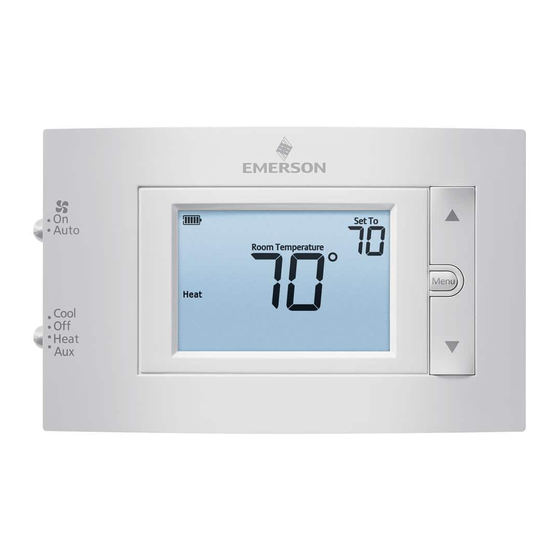
USER MENU USING THE THERMOSTAT To customize thermostat settings, press the Menu button from the home screen. Use Next to advance through menu items. Press to change the setting. THERMOSTAT OVERVIEW Before you begin using your thermostat, you should be familiar with its features, display and the location/operation of the thermostat buttons and switches. -
Page 4: Troubleshooting
Display can be adjusted +/-5°. See User Menu Thermometer adjustment item 04 Disagree HOMEOWNER HELP LINE: 1-800-284-2925 (Troubleshooting continued on next page) White-Rodgers is a business of Emerson Electric Co. The Emerson logo is a trademark and service mark www.white-rodgers.com of Emerson Electric Co. www.emersonclimate.com...
Need help?
Do you have a question about the 1F83H-21NP and is the answer not in the manual?
Questions and answers
what terminal does the emergency heat go on