Table of Contents
Advertisement
Available languages
Available languages
Quick Links
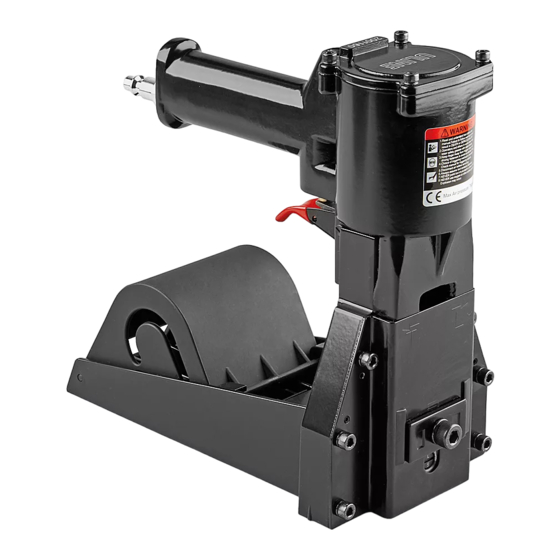
H-1030
H-1031
PNEUMATIC ROLL
STAPLER
• Read the manual and understand all safety
instructions before operating the tool. If you have
questions, contact Uline at 1-800-295-5510.
• Never point the stapler towards you or anyone else.
• Never use flammable gases as a power source for
the stapler. Only use filtered, compressed air.
• Never use gasoline or other flammable liquids to
clean the stapler. Vapors left on the stapler could
ignite and cause the tool to explode.
• Do not exceed 110 psi of air pressure when
operating the stapler.
• Disconnect the stapler from the air supply before
making adjustments, cleaning or clearing jams
and when not in use.
• Do not pull the trigger when carrying or holding
the stapler.
PAGE 1 OF 24
1-800-295-5510
uline.com
SPECIFICATIONS
Dimensions (L x H x W)
Weight (Without Fasteners)
Maximum PSI (Compressed Air)
Recommended Operating Pressure
Air Consumption
Staple Specification
Staple Specification
Staple Capacity
Noise Level
9 x 9 x 4.5"
70-110 psi
2.4 CFM
S-860 RR1-58 Roll
S-861 RR1-34 Roll
1,000 Staples
89 dBA
SAFETY
• Never carry the stapler by the hose or pull on
the hose to move the stapler.
• Always wear protective equipment; i.e. safety
glasses with side shields, hearing protection and
head protection.
• Do not use a check valve or any other fitting which
allows air to remain in the stapler.
• Do not place your hand or any other body part in
the staple clinching area or adjustment window
when connecting or disconnecting the air supply.
• Ensure that anyone in the vicinity wears safety
protection.
• Check and replace any damaged or worn
components on the stapler
Para Español, vea páginas 9-16.
Pour le français, consulter les pages 17-24.
5.5 lb.
110 psi
0323 IH-1030
Advertisement
Table of Contents

Related Manuals for U-Line H-1030


Summary of Contents for U-Line H-1030
- Page 1 Para Español, vea páginas 9-16. Pour le français, consulter les pages 17-24. H-1030 1-800-295-5510 H-1031 uline.com PNEUMATIC ROLL STAPLER SPECIFICATIONS Dimensions (L x H x W) 9 x 9 x 4.5" Weight (Without Fasteners) 5.5 lb. Maximum PSI (Compressed Air)
-
Page 2: Lubrication And Maintenance
SETUP LUBRICATION & MAINTENANCE AIR SUPPLY AND CONNECTIONS 1. Lubricate stapler prior to initial operation. Ensure air supply system is setup correctly for increased the efficiency and life of the stapler. (See Figure 1) 2. Disconnect the stapler from the air supply prior to servicing. -
Page 3: Clinch Adjustment
OPERATION CONTINUED STAPLE LEG LENGTH CLINCH ADJUSTMENT 1. Loosen the set screw on the bottom with a 3 mm Allen Use 2.5 mm Allen wrench and turn collar through window wrench. (See Figure 4) clockwise to tighten clinch. (See Figure 7-9) Figure 7 Tight Medium... -
Page 4: Depth Adjustment
OPERATION CONTINUED DEPTH ADJUSTMENT 4. If set at No. 1 the teeth are at their deepest penetration. (See Figure 13) 1. Loosen front screw with a 6 mm Allen wrench. (See Figure 10) Figure 10 No. 1 No. 2 & 3 No. -
Page 5: Teeth Replacement
OPERATION CONTINUED TEETH REPLACEMENT CONNECTING TO AIR 1. Loosen screws and nut with an 8 mm wrench and 1. Add a few drops of oil into the air inlet. a 4 mm Allen wrench. (See Figure 15) 2. Install a quick connect fitting to the stapler. Figure 15 3. -
Page 6: Valve And Tube O-Ring Replacement
OPERATION CONTINUED VALVE AND TUBE O-RING REPLACEMENT 4. Loosen the set screw with a 3 mm Allen wrench to unlock the adjusting rod. 1. Loosen screws with a flat screwdriver. (See Figure 23) 5. Slide the linkage mechanism and adjusting rod simultaneously from the collar. -
Page 7: Piston Replacement
OPERATION CONTINUED 4. Remove valve and tube with needle-nose pliers. 5. Loosen collar with a 3 mm straight rod to remove the (See Figure 26) spring. (See Figure 29) Valve and Tube Figure 29 Figure 26 6. Loosen screw with a 3 mm Allen wrench and remove the block through the window. -
Page 8: Troubleshooting
TROUBLESHOOTING WARNING! Stop using the stapler immediately if any of the following problems occur. Serious personal injury could occur. Any repairs or replacements must be done by a qualified person or authorized service center only. PROBLEM CAUSE SOLUTION Air leak from trigger O-ring on valve or on tube is Replace O-ring. -
Page 9: Especificationes
H-1030 800-295-5510 H-1031 uline.mx ENGRAPADORA NEUMÁTICA DE ROLLO ESPECIFICATIONES Dimensiones (LA x AL x AN): 23 x 23 x 11.5 cm (9 x 9 x 4.5") Peso (sin cinchos): 2.5 kg (5.5 lbs.). PSI Máximo (Aire comprimido): 110 psi Presión operativa Recomendada:... -
Page 10: Lubricación Y Mantenimiento
CONFIGURACIÓN LUBRICACIÓN Y MANTENIMIENTO SUMINISTRO DE AIRE Y CONEXIONES 1. Lubrique la engrapadora antes de la operación Assurez-vous que le système d'alimentation en air est inicial. correctement configuré pour augmenter l'efficacité et la durée de vie de l'agrafeuse. (Vea Diagrama 1) 2. - Page 11 CONTINUACIÓN DE FUNCIONAMIENTO LARGO DE PATA DE LA GRAPA AJUSTE DE REMACHE 1. Afloje el tornillo de ajuste de la parte inferior con una Utilice una llave Allen de 2.5 mm y gire el collarín llave Allen de 3 mm. (Vea Diagrama 4) hacia la derecha a través de la ventana para apretar el remache.
-
Page 12: Ajuste De Profundidad
CONTINUACIÓN DE FUNCIONAMIENTO AJUSTE DE PROFUNDIDAD 4. Si está configurado en el No. 1, los dientes están en su penetración más profunda. (Vea Diagrama 13) 1. Afloje el tornillo frontal con una llave Allen de 6 mm. (Vea Diagrama 10) Diagrama 10 No. - Page 13 CONTINUACIÓN DE FUNCIONAMIENTO REEMPLAZO DE DIENTES CONEXIÓN AL AIRE 1. Afloje los tornillos y la tuerca con una llave de 8 mm 1. Agregue unas gotas de aceite en la entrada de aire. y una llave Allen de 4 mm. (Vea Diagrama 15) 2.
- Page 14 CONTINUACIÓN DE FUNCIONAMIENTO REEMPLAZAR LA VÁLVULA Y EL TUBO 4. Afloje el tornillo de ajuste con una llave Allen de 3 mm para destrabar la varilla de ajuste. DEL ANILLO-O 5. Retire el mecanismo de unión y ajuste la varilla 1.
- Page 15 CONTINUACIÓN DE FUNCIONAMIENTO 4. Retire la válvula y el tubo con pinzas de punta fina. 5. Afloje el collarín con una varilla recta de 3 mm para (Vea Diagrama 26) retirar el resorte. (Vea Diagrama 29) La Válvula y el Tubo Del Anillo-O Diagrama 29 Diagrama 26...
-
Page 16: Solución De Problemas
SOLUCIÓN DE PROBLEMAS ¡ADVERTENCIA! Deje de usar la engrapadora de inmediato si presenta cualquiera de los siguientes problemas. Podrían ocurrir lesiones personales graves. Todas las reparaciones o reemplazos deben ser realizados solamente por una persona calificada o en un centro de servicios autorizado. PROBLEMA CAUSA REMEDIO... -
Page 17: Specifications
H-1030 1-800-295-5510 H-1031 uline.ca AGRAFEUSE PNEUMATIQUE À ROULEAU SPECIFICATIONS Dimensions (long. x haut. x larg.) 23 x 23 x 11,5 cm (9 x 9 x 4,5 po) Poids (sans agrafes) 2,5 kg (5,5 lb) Pression maximum (Air comprimé) 6,9 bars (110 lb/po²) 4,9 à 6,9 bars Pression de service recommandée (70 à 100 lb/po²) Débit d'air 0,07 mcm (2,4 pcm) Spécification des agrafes Rouleau S-860 RR1-58 Spécification des agrafes... -
Page 18: Installation
INSTALLATION LUBRIFICATION ET ENTRETIEN ALIMENTATION EN AIR ET RACCORDS 1. Lubrifiez l'agrafeuse avant son utilisation initiale. L'illustration ci-dessous présente le mode de raccordement approprié au système d'alimentation en air, qui 2. Déconnectez l'agrafeuse de la source d'alimentation augmentera l'efficacité et la durée de vie de l'agrafeuse. d'air avant tout entretien. - Page 19 OPÉRATION SUITE LONGUEUR DE PATTE D'AGRAFE RÉGLAGE DE LA FERMETURE 1. Desserrez la vis de réglage qui se trouve sous Serrez la fermeture en tournant le collet dans le l'agrafeuse à l'aide d'une clé Allen 3 mm. sens horaire à travers la fenêtre à l'aide d'une (Voir Figure 4) clé...
-
Page 20: Réglage De La Profondeur
OPÉRATION SUITE RÉGLAGE DE LA PROFONDEUR 4. Si réglées au N° 1, les dents présentent la pénétration la plus profonde. (Voir Figure 13) 1. Desserrez la vis avant à l'aide d'une clé Allen 6 mm. (Voir Figure 10) Figure 10 N° 1 N°... - Page 21 OPÉRATION SUITE REMPLACEMENT DE DENTS CONNEXION D'AIR 1. Desserrez les vis et l'écrou à l'aide d'une clé 8 mm 1. Déposez quelques gouttes d'huile dans l'entrée d'air. et d'une clé Allen 4 mm. (Voir Figure 15) 2. Installez un raccord à branchement rapide sur l'agrafeuse.
- Page 22 OPÉRATION SUITE REMPLACEMENT DU JOINT TORIQUE DE 4. Pour déverrouiller la tige de réglage, desserrez la vis de réglage à l'aide d'une clé Allen 3 mm. SOUPAPE ET TUBE 5. Glissez simultanément les liens et la tige de réglage 1. Desserrez les vis à l'aide d'un tournevis à lame plate. pour les éloigner du collet.
- Page 23 OPÉRATION SUITE 4. Retirez la soupape et le tube à l'aide d'une pince à 5. Pour retirer le ressort, desserrez le collet à l'aide d'une bec effilé. (Voir Figure 26) clé Allen 3 mm. (Voir Figure 29) Joint Torique De Soupape Et Tube Figure 29 Figure 26 6.
-
Page 24: Dépannage
DÉPANNAGE Cessez immédiatement d'utiliser l'agrafeuse si l'un ou l'autre des problèmes suivants se produit. ARRÊT De graves blessures corporelles pourraient s'en suivre. Tout remplacement ou réparation doit être réalisé(e) uniquement par une personne qualifiée ou par un centre de service autorisé. PROBLÈME CAUSE CORRECTIF...
Need help?
Do you have a question about the H-1030 and is the answer not in the manual?
Questions and answers