Sign In
Upload
Download
Add to my manuals
Delete from my manuals
Share
URL of this page:
HTML Link:
Bookmark this page
Add
Manual will be automatically added to "My Manuals"
Print this page
×
Bookmark added
×
Added to my manuals
Manuals
Brands
AMS Manuals
Accessories
AS5306
User manual
AMS AS5306 User Manual
Demo kit, 160-step linear incremental position sensor with abi output
Hide thumbs
1
Table Of Contents
2
3
4
5
6
7
8
9
10
11
12
13
page
of
13
Go
/
13
Contents
Table of Contents
Bookmarks
Advertisement
Quick Links
Download this manual
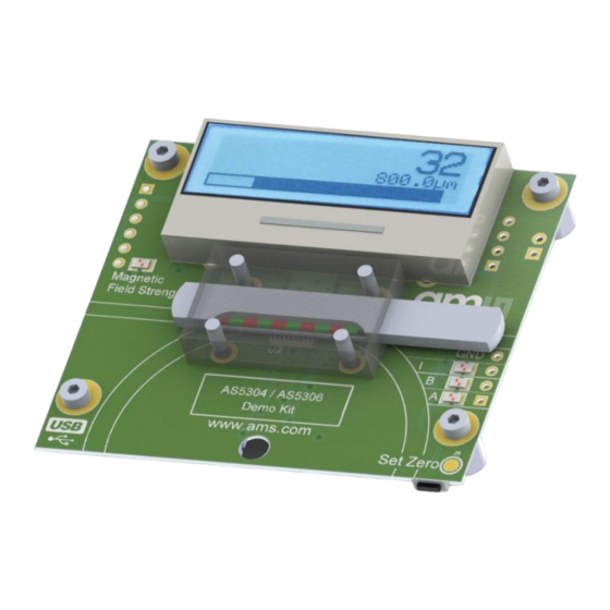
User Manual – AS5304 / AS5306 Demo Kit
AS5304 / AS5306
160-step Linear Incremental Position
Sensor with ABI output
www.ams.com
Revision 1.3 / 2012/09/24
Table of
Contents
Previous
Page
Next
Page
1
2
3
4
5
Advertisement
Need help?
Do you have a question about the AS5306 and is the answer not in the manual?
Ask a question
Questions and answers
Related Manuals for AMS AS5306
Accessories AMS AS5048 User Manual
14-bit rotary position sensor with digital angle (interface) and pwm output (12 pages)
Accessories AMS AS5262 User Manual
Adapterboard, 12 bit magnetic angle position sensor with 2 outputs (11 pages)
Accessories AMS AS5x61 Series Programming Manual
(14 pages)
Accessories AMS AS7225 User Manual
Director demo kit (16 pages)
Accessories AMS AS5600 Operation Manual
12-bit programmable contactless potentiometer (12 pages)
Accessories AMS AS5304 User Manual
Demo kit, 160-step linear incremental position sensor with abi output (13 pages)
Accessories AMS AS7221 User Manual
Smart lighting integration kit (slik) (17 pages)
Accessories AMS AS5170 Series Datasheet
High-resolution on-axis magnetic angular position sensor (48 pages)
Accessories AMS AS5263 Operation Manual
(8 pages)
Accessories AMS AS8579-TS EK DB User Manual
Demokit capacitive sensor (10 pages)
Accessories AMS TSL2520 Quick Start Manual
Highly sensitive ambient light sensor (9 pages)
Accessories AMS Kombi Alarm Installation And Operating Instrucitons
(4 pages)
Accessories AMS TCS3701 Quick Start Manual
Als/color and proximity sensor for use behind oled displays evaluation kit (8 pages)
Accessories AMS TSL2585 Quick Start Manual
Miniature ambient light sensor with uv and light flicker detection (9 pages)
Accessories AMS TMD2755 Quick Start Manual
Als and proximity sensor module (8 pages)
Accessories AMS TCS3720 Quick Start Manual
(9 pages)
This manual is also suitable for:
As5304
Print
Rename the bookmark
Delete bookmark?
Delete from my manuals?
Login
Sign In
OR
Sign in with Facebook
Sign in with Google
Upload manual
Upload from disk
Upload from URL


Need help?
Do you have a question about the AS5306 and is the answer not in the manual?
Questions and answers