
Subscribe to Our Youtube Channel
Related Manuals for Amazone Citan 12001-C


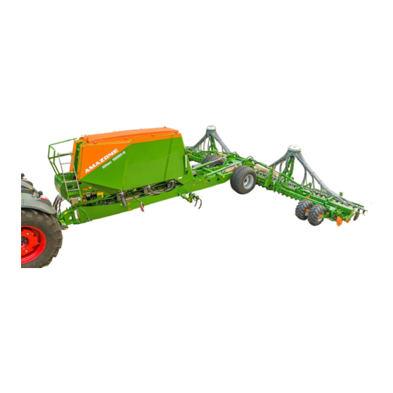
Summary of Contents for Amazone Citan 12001-C
- Page 1 Operating instructions Large area seed drill Citan 12001-C Citan 15001-C Please read this operating manual before initial MG5594 operation. BAH0039-2 07.15 Keep it in a safe place for future use!
- Page 2 Only this way, you would be satisfied both with the machine as also with yourself. To achieve this is the purpose of this instruction manual. Leipzig-Plagwitz 1872. Citan 12001-C/15001-CCitan 12001-C/15001-C BAH0039-2 07.15...
- Page 3 Document number: MG5594 Compilation date: 07.15 Copyright AMAZONEN-WERKE H. DREYER GmbH & Co. KG, 2014 All rights reserved. Reprinting, even of sections, only possible with the approval of AMAZONEN-WERKE H. DREYER GmbH & Co. KG. Citan 12001-C/15001-CCitan 12001-C/15001-C BAH0039-2 07.15...
- Page 4 Send us your suggestions by fax. AMAZONEN-WERKE H. DREYER GmbH & Co. KG Postfach 51 D-49202 Hasbergen, Germany Tel.: + 49 (0) 5405 501-0 Fax: + 49 (0) 5405 501-234 E-mail: amazone@amazone.de Citan 12001-C/15001-CCitan 12001-C/15001-C BAH0039-2 07.15...
-
Page 5: Table Of Contents
Parking brake ......................... 51 5.2.2 Dual-circuit pneumatic braking system .................. 52 5.2.2.1 Coupling the brake and supply lines ..................53 5.2.2.2 Uncoupling the supply and brake line ..................55 Citan 12001-C/15001-CCitan 12001-C/15001-C BAH0039-2 07.15... - Page 6 Roller harrow (optional) ......................78 5.20 Seed drill wheel mark eradicator (optional) ................78 5.21 Track marker (optional, only for Citan 12001-C) ..............78 5.22 One-sided switching off (part-width section) ................. 79 5.23 Creation of tramlines ......................
- Page 7 Adjusting the roller pressure ....................131 8.11 Adjusting the seed drill wheel mark eradicators ..............132 8.12 Adjusting the track marker (only for Citan 12001-C) ............133 8.13 Setting the tramline rhythm/counter ..................134 8.14 Half-sided switching off ......................
- Page 8 Display of amount remaining ....................158 11.2 Fault table ..........................159 11.3 Triggering the track marker safety (Citan 12001-C) ............159 Cleaning, maintenance and repairs ............160 12.1 Securing the connected implement ..................161 ...
-
Page 9: User Information
Numbers in round brackets refer to the item numbers in the diagrams. The first number refers to the diagram and the second number to the item. Example: (Fig. 3/6) Figure 3 Item 6 Citan 12001-C/15001-CCitan 12001-C/15001-C BAH0039-2 07.15... -
Page 10: General Safety Instructions
If this is not the task of the user or if the user does not possess the appropriate technical knowledge, then they should report this fault to their superior (operator). Citan 12001-C/15001-CCitan 12001-C/15001-C BAH0039-2 07.15... - Page 11 Unauthorised design changes to the implement Insufficient monitoring of implement parts which are subject to wear Improperly executed repairs Disasters due to the effects of foreign objects and force majeure Citan 12001-C/15001-CCitan 12001-C/15001-C BAH0039-2 07.15...
-
Page 12: Representation Of Safety Symbols
Non-compliance with these instructions can cause faults on the implement or disturbance to the environment. NOTE Indicates handling tips and particularly useful information. These instructions will help you to use all the functions of your implement in the best way possible. Citan 12001-C/15001-CCitan 12001-C/15001-C BAH0039-2 07.15... -
Page 13: Organisational Measures
As well as all the safety information in this operating manual, comply with the general, national regulations pertaining to accident prevention and environmental protection. When driving on public roads and routes you should comply with the statutory road traffic regulations. Citan 12001-C/15001-CCitan 12001-C/15001-C BAH0039-2 07.15... -
Page 14: User Training
"Workshop". The personnel of a specialist workshop shall possess the appropriate knowledge and suitable aids (tools, lifting and support equipment) for carrying out the maintenance and repair work on the implement in a way which is both appropriate and safe. Citan 12001-C/15001-CCitan 12001-C/15001-C BAH0039-2 07.15... -
Page 15: Safety Measures In Normal Operation
Carefully fix and secure larger assemblies to lifting gear when carrying out replacement work. Check all the bolted connections for tightness. On completion of the maintenance work, check the function of the safety devices. Citan 12001-C/15001-CCitan 12001-C/15001-C BAH0039-2 07.15... -
Page 16: Design Changes
It is strictly forbidden to drill holes in the frame or on the running gear. increase the size of existing holes on the frame or the running gear. weld support parts. Citan 12001-C/15001-CCitan 12001-C/15001-C BAH0039-2 07.15... -
Page 17: Spare And Wear Parts And Aids
Immediately replace any implement parts which are not in a perfect state. Use only genuine AMAZONE spare and wear parts or the parts cleared by AMAZONEN-WERKE so that the operating permit retains its validity in accordance with national and international regulations. If... -
Page 18: Warning Symbols And Other Labels On The Implement
2. The consequence of non-compliance with the risk avoidance instructions. For example: causes serious injuries to fingers or hands. 3. Risk avoidance instructions. For example: only touch implement parts when they have come to a complete standstill. Citan 12001-C/15001-CCitan 12001-C/15001-C BAH0039-2 07.15... - Page 19 It is forbidden to stand in the swivel range of the implement when implement parts are being lowered. Instruct personnel to leave the swivel range of any implement parts which can be lowered before you lower the parts. Citan 12001-C/15001-CCitan 12001-C/15001-C BAH0039-2 07.15...
- Page 20 Actuate the operating controls for the tractor's three-point hydraulic system only from the designated workstation. under no circumstances if you are in the lifting area between the tractor and implement. Citan 12001-C/15001-CCitan 12001-C/15001-C BAH0039-2 07.15...
- Page 21 Secure the tractor and the implement against unintentional start-up and rolling before any intervention in the implement. Depending on the type of intervention, read and understand the information in the relevant sections of the operating manual. Citan 12001-C/15001-CCitan 12001-C/15001-C BAH0039-2 07.15...
- Page 22 Ensure that all personnel maintain an adequate safety distance from moving implement parts. MD 110 This pictogram identifies parts of the implement that serve as a handle. MD 114 This symbol indicates a lubrication point Citan 12001-C/15001-CCitan 12001-C/15001-C BAH0039-2 07.15...
- Page 23 Never use the water from the hand wash tank as drinking water. The materials used to construct the fresh water tank are not food-safe. MD 199 The maximum operating pressure of the hydraulic system is 210 bar Citan 12001-C/15001-CCitan 12001-C/15001-C BAH0039-2 07.15...
- Page 24 Instruct people to leave the danger area between the tractor and the implement whenever the engine of the tractor is running and the tractor is not secured against unintentional rolling. Citan 12001-C/15001-CCitan 12001-C/15001-C BAH0039-2 07.15...
-
Page 25: Positions Of Warning Symbols And Other Labels
General Safety Instructions 2.13.1 Positions of warning symbols and other labels Warning symbols The following diagrams show the arrangement of the warning symbols on the implement. Fig. 1 Fig. 2 Citan 12001-C/15001-CCitan 12001-C/15001-C BAH0039-2 07.15... -
Page 26: Dangers If The Safety Information Is Not Observed
Comply with the accident prevention instructions on the warning symbols. When driving on public roads and routes, comply with the appropriate statutory road traffic regulations. Citan 12001-C/15001-CCitan 12001-C/15001-C BAH0039-2 07.15... -
Page 27: Safety Information For Users
Any helpers may only act as guides standing next to the vehicles, and may only move between the vehicles when both are at a standstill. Citan 12001-C/15001-CCitan 12001-C/15001-C BAH0039-2 07.15... - Page 28 must not chafe against other parts. The release ropes for quick action couplings must hang loosely and may not release themselves when lowered. Also ensure that uncoupled implements are stable! Citan 12001-C/15001-CCitan 12001-C/15001-C BAH0039-2 07.15...
- Page 29 The front tractor axle must always be loaded with at least 20 % of the empty tractor weight, in order to ensure sufficient steering power. Always fix the front or rear weights to the intended fixing points according to regulations. Citan 12001-C/15001-CCitan 12001-C/15001-C BAH0039-2 07.15...
- Page 30 Adjust your forward speed to the prevailing conditions. Before driving downhill, switch to a low gear. Before road transport, always switch off the independent wheel braking (lock the pedals). Citan 12001-C/15001-CCitan 12001-C/15001-C BAH0039-2 07.15...
-
Page 31: Hydraulic System
Replace the hydraulic hose lines if they are damaged or worn. Only use original AMAZONE hydraulic hose lines. The hydraulic hose lines should not be used for longer than six years, including any storage time of maximum two years. Even... -
Page 32: Electrical System
Only a specialist workshop may adjust the height of the drawbar on yoke bars with a drawbar load. Citan 12001-C/15001-CCitan 12001-C/15001-C BAH0039-2 07.15... -
Page 33: Brake System
Hydraulic brake system for export implements Hydraulic brake systems are not approved in Germany. When filling up or replacing the brake fluid, use the prescribed hydraulic fluids. When replacing the hydraulic fluids, comply with the appropriate regulations. Citan 12001-C/15001-CCitan 12001-C/15001-C BAH0039-2 07.15... -
Page 34: Tyres
Spare parts must meet at least the specified technical requirements of AMAZONEN-WERKE! This is ensured through the use of original AMAZONE spare parts. Citan 12001-C/15001-CCitan 12001-C/15001-C BAH0039-2 07.15... -
Page 35: Loading And Unloading
2. Place the implement on the transport vehicle and lash it down as prescribed. Fig. 4 The (Fig. 5) symbol marks the lashing points on the implement. Fig. 5 Fig. 6/… (1) Front lashing points Fig. 6 Citan 12001-C/15001-CCitan 12001-C/15001-C BAH0039-2 07.15... - Page 36 Loading and unloading Fig. 7/… (1) Middle lashing points (2/3) Rear lashing points Fig. 7 Citan 12001-C/15001-CCitan 12001-C/15001-C BAH0039-2 07.15...
-
Page 37: Product Description
(1) Seed hopper, 3 chambers (6) Roller harrow, (optionally exact following harrow) (2) Metering (7) Support wheel (3) Distributor head for seed-fertiliser mixture (8) Running gear (4) Seed hose (9) Wheel chocks (5) RoTeC coulter Citan 12001-C/15001-CCitan 12001-C/15001-C BAH0039-2 07.15... -
Page 38: Overview Of Assembly Groups
Product description Overview of assembly groups Fig. 9/... Control terminal AMALOG Fig. 9 Fig. 10/... (1) Tensioned crosspiece (2) Loading board with ladder (pivoting) Fig. 10 Fig. 11/... (1) Mounting for supply lines Fig. 11 Citan 12001-C/15001-CCitan 12001-C/15001-C BAH0039-2 07.15... - Page 39 of a metering roller of the digital scale Fig. 12 Fig. 13/... (1) Star wheel (lifted) (2) Calibration crank Fig. 13 Fig. 14/... RoTeC coulter Fig. 14 Fig. 15/... RoTeC-Pro coulter Fig. 15 Citan 12001-C/15001-CCitan 12001-C/15001-C BAH0039-2 07.15...
- Page 40 (1) Seed tube monitoring (optional) The seed tube hoses represent the connection between the distributor head and the coulters. Each seed tube hose can be equipped with a sensor (Fig. 18/1) that detects the seed flow. Fig. 18 Citan 12001-C/15001-CCitan 12001-C/15001-C BAH0039-2 07.15...
-
Page 41: Safety And Protective Equipment
(1) Catch hooks (for locking the implement sections during transportation) Fig. 20 Fig. 21/… (1) Catch hooks (locks the implement sections) Fig. 21 Fig. 22/… (1) Wheel chocks (parking position under the seed hopper) Fig. 22 Citan 12001-C/15001-CCitan 12001-C/15001-C BAH0039-2 07.15... -
Page 42: Transportation Equipment
(5) 2 reflectors, triangular Fig. 24 Fig. 25/... (1) 2 forwards-facing limiting lights (2) 2 forwards-facing warning signs Fig. 25 Fig. 26/... (1) 2 x 4 reflectors, yellow, (laterally with a max. spacing of 3 m) Fig. 26 Citan 12001-C/15001-CCitan 12001-C/15001-C BAH0039-2 07.15... -
Page 43: Overview - Supply Lines Between The Tractor And The Implement
Compliance with all the instructions in this operating manual. Adherence of inspection and maintenance work. Exclusive use of original AMAZONE spare parts. Other uses to those specified above are forbidden and shall be considered as improper. For any damage resulting from improper use ... -
Page 44: Danger Areas And Danger Points
in the area of the swivelling implement sections. underneath raised, unsecured implements or parts of implements. When folding and unfolding the implement sections near overhead power lines. Citan 12001-C/15001-CCitan 12001-C/15001-C BAH0039-2 07.15... -
Page 45: Rating Plate And Ce Mark
(4) Perm. system pressure total weight (kg) (5) Perm. system pressure Front axle load/drawbar load (kg) (6) Perm. system pressure rear axle load (7) Perm. system pressure system pressure (bar) Fig. 29 (8) Factory (9) Model year (10) Year of manufacture Citan 12001-C/15001-CCitan 12001-C/15001-C BAH0039-2 07.15... -
Page 46: Technical Data
(see rating plate) without [km/h] brake system with dual-circuit Permissible max. pneumatic braking [km/h] speed system with hydraulic [km/h] brake system Operation without a brake system is not permitted in Germany and in several other countries. Citan 12001-C/15001-CCitan 12001-C/15001-C BAH0039-2 07.15... -
Page 47: Necessary Tractor Equipment
The workplace-related emission value (acoustic pressure level) is 74 dB(A), measured in operating condition at the ear of the tractor driver with the cab closed. Measuring unit: OPTAC SLM 5. The noise level is primarily dependent on the vehicle used. Citan 12001-C/15001-CCitan 12001-C/15001-C BAH0039-2 07.15... -
Page 48: Layout And Function
(Fig. 30/7) with the adjustable drag tines can be used. The implement can be folded to a transport width of 3 m and transported on the running gear (Fig. 30/8). Citan 12001-C/15001-CCitan 12001-C/15001-C BAH0039-2 07.15... -
Page 49: Hydraulic Hose Lines
(neutral position). 2. Clean the hydraulic connectors of the hydraulic hose lines before you couple the hydraulic hose lines to the tractor. 3. Connect the hydraulic hose line(s) to the tractor control unit(s). Fig. 31 Citan 12001-C/15001-CCitan 12001-C/15001-C BAH0039-2 07.15... -
Page 50: Uncoupling The Hydraulic Hose Lines
2. Release the hydraulic connectors from the hydraulic sockets. 3. Protect the hydraulic connectors and hydraulic connector sockets from soiling using the dust protection caps. Fig. 32 4. Place the hydraulic hose lines in the hose cabinet. Fig. 33 Citan 12001-C/15001-CCitan 12001-C/15001-C BAH0039-2 07.15... -
Page 51: Service Brake System
The crank (Fig. 34/1) is used to activate the parking brake. Engaging the parking brake: Turn the crank to the right (R). Releasing the parking brake: Turn the crank to the left (L). Fig. 34 Citan 12001-C/15001-CCitan 12001-C/15001-C BAH0039-2 07.15... -
Page 52: Dual-Circuit Pneumatic Braking System
The dual-circuit pneumatic brake system has a supply line (Fig. 35/1) with coupling head (red). a brake line (Fig. 35/2) with coupling head (yellow). Fig. 35 a trailer brake valve (Fig. 36/1). Fig. 36 Citan 12001-C/15001-CCitan 12001-C/15001-C BAH0039-2 07.15... -
Page 53: Coupling The Brake And Supply Lines
4. Clean the dirty sealing rings and replace any damaged sealing rings. 5. Fasten the hose coupling of the brake line (yellow) in compliance with regulations in the coupling marked yellow (Fig. 37/2) on Fig. 37 the tractor. Citan 12001-C/15001-CCitan 12001-C/15001-C BAH0039-2 07.15... - Page 54 In an emergency, pull the red button (Fig. 38/1) to brake the implement. The implement does not have any braking effect if the tractor parking brake is released when the supply line (red) is connected. Fig. 38 Citan 12001-C/15001-CCitan 12001-C/15001-C BAH0039-2 07.15...
-
Page 55: Uncoupling The Supply And Brake Line
DANGER First secure the implement with the wheel chocks (Fig. 39) before you uncouple the implement from the tractor! Fig. 39 Fig. 40/… (1) Wheel chocks (parking position under the seed hopper) Fig. 40 Citan 12001-C/15001-CCitan 12001-C/15001-C BAH0039-2 07.15... -
Page 56: Control Elements Of The Dual-Circuit Pneumatic Braking System
When the supply line (red) is coupled to the tractor, the parking brake is released automatically, and as soon as the operating pressure has built up, the black button (Fig. 42/1) will be automatically pulled out of the valve chest. Citan 12001-C/15001-CCitan 12001-C/15001-C BAH0039-2 07.15... -
Page 57: Hydraulic Operating Brake System
1. Release the hydraulic connectors from the hydraulic sockets. 2. Secure the hydraulic socket and hydraulic connector with protective caps (Fig. 44/1) against soiling. 3. Place the hydraulic hose line on the holder for the supply lines. Fig. 44 Citan 12001-C/15001-CCitan 12001-C/15001-C BAH0039-2 07.15... -
Page 58: Control Terminal Amalog
shows the current blower fan speed. initiates an alarm when the blower fan speed deviates from the nominal value. Citan 12001-C/15001-CCitan 12001-C/15001-C BAH0039-2 07.15... -
Page 59: Frame And Implement Sections
(Fig. 46/5). Threaded cartridge The threaded cartridges (Fig. 47/1) include the accessories kit with the operating manual, the metering rollers in parking position, the scales for the calibration test. Fig. 47 Citan 12001-C/15001-CCitan 12001-C/15001-C BAH0039-2 07.15... -
Page 60: Hopper
When the blower fan is running, the hopper cover (Fig. 49/1) must be firmly closed (see section "Filling the hopper", page 147). Fig. 49 A pressure gauge (Fig. 50/1) indicates the pressure in the sealed delivery system. Fig. 50 Citan 12001-C/15001-CCitan 12001-C/15001-C BAH0039-2 07.15... - Page 61 Each hopper chamber is marked with a number (Fig. 52/1) on the metering unit. Fig. 52 The pressure gauges on the loading board (Fig. 53/1) indicate the pressures in the individual hopper chambers. Fig. 53 Citan 12001-C/15001-CCitan 12001-C/15001-C BAH0039-2 07.15...
-
Page 62: Digital Fill Level Monitoring
Attach the sensor in the upper or lower bracket, Fig. 55 depending on the spread rate. This allows the residual seed volume to be set, at which the warning message and the alarm signal is to be issued. Citan 12001-C/15001-CCitan 12001-C/15001-C BAH0039-2 07.15... -
Page 63: Hand Wash Tank
The materials of the hand wash tank are not food safe. Fig. 57 Work lights (optional) Fig. 58/... (1) Work floodlights Separate power supply from the tractor is required. Fig. 58 Citan 12001-C/15001-CCitan 12001-C/15001-C BAH0039-2 07.15... -
Page 64: Quick Emptying (Optional)
3. Slowly open the quick emptying with the lever. 4. Clean the sealing area of the quick emptying before putting back into operation. 5. Close the quick emptying. 6. Secure the lever (Fig. 59/1) using the knurled screw (Fig. 59/2). Fig. 59 Citan 12001-C/15001-CCitan 12001-C/15001-C BAH0039-2 07.15... -
Page 65: Seed/Fertiliser Metering
Fig. 61 The seed or fertiliser falls into the delivery tube (Fig. 62/1). The air current generated by the blower fan conveys the seed/fertilizer mixture to the distributor head and then onto the coulters. Fig. 62 Citan 12001-C/15001-CCitan 12001-C/15001-C BAH0039-2 07.15... -
Page 66: Metering Rollers
the metered material (seed/fertiliser), the spread rate. Fit all of the seed metering units with the same metering roller. Fit the fertiliser metering unit with the fertiliser metering roller. 7.5 cm 20 cm Citan 12001-C/15001-CCitan 12001-C/15001-C BAH0039-2 07.15... - Page 67 Layout and function 40 cm 120 cm 210 cm 350 cm 600 cm 660 cm 880 cm Fig. 64 Citan 12001-C/15001-CCitan 12001-C/15001-C BAH0039-2 07.15...
-
Page 68: 5.10.1.1 Metering Rollers Table
Buckwheat Spelt Fertiliser (granular) Peas Flax (dressed) Barley Grass seed Oats Millet Caraway Lupins Alfalfa Maize Poppy seed Oil linen (moist dressing) Fodder radish Phacelia Rapeseed Rice Red clover Mustard Sunflowers Turnips Triticale Wheat Vetches Citan 12001-C/15001-CCitan 12001-C/15001-C BAH0039-2 07.15... -
Page 69: 5.10.1.1 Converting The Metering Roller
The reduce the metering rate, replace the metering wheels by idler gears. 5.10.1.2 Fertiliser metering roller The fertiliser metering unit is equipped with a fertiliser metering roller (Fig. 67/1) that is suitable for all fertiliser types (see Metering Rollers Table, page 68). Fig. 67 Citan 12001-C/15001-CCitan 12001-C/15001-C BAH0039-2 07.15... -
Page 70: Adjusting The Spread Rate (Seed And Fertiliser) On The Vario Gearbox
30 kg/ha An inner white scale (Fig. 69/2) for all spread rates below 30 kg/ha A coloured scale (Fig. 69/3) Fig. 69 with all gearbox settings from 1 to 100. Citan 12001-C/15001-CCitan 12001-C/15001-C BAH0039-2 07.15... -
Page 71: Calibration Test
Fig. 70 When not in use, the calibration troughs (Fig. 71/1) are inserted inside one another and secured in the transport bracket using a linch pin (Fig. 72/1). Fig. 71 Fig. 72 Citan 12001-C/15001-CCitan 12001-C/15001-C BAH0039-2 07.15... -
Page 72: Blower Fan
The fan speed is set correctly when the indicator for the pressure gauge is between 45 and 60 mbar. At an idle, pressures between 25 and 35 bar are reached in the individual hopper chambers. Fig. 74 Citan 12001-C/15001-CCitan 12001-C/15001-C BAH0039-2 07.15... -
Page 73: Distributor Head
The star wheel controls the creation of tramlines. Approx. 5 seconds after each time the star wheel is swivelled up, e.g. before turning at the end of the field, the tramline counter is advanced. Fig. 77 Citan 12001-C/15001-CCitan 12001-C/15001-C BAH0039-2 07.15... -
Page 74: Rotec + Coulter
(Fig. 79/2). The steady coulter ride and the precise seed Fig. 79 placement result from the high coulter pressure and the support of the coulter on the depth limiting. Citan 12001-C/15001-CCitan 12001-C/15001-C BAH0039-2 07.15... -
Page 75: Seed Placement Depth
(Fig. 78/3). improves the drive of the seeding disc by gripping the soil. The "Control 25" depth limiting roller (Fig. 81) permits shallow seeding, even on very light soils. Fig. 81 Citan 12001-C/15001-CCitan 12001-C/15001-C BAH0039-2 07.15... -
Page 76: Coulter Pressure
If the pressure gauge is depressurised: The coulters work with normal coulter pressure. If the pressure gauge is pressurised: The coulters work with increased coulter pressure. Set the required coulter pressure with the blue tractor control unit. Fig. 83 Citan 12001-C/15001-CCitan 12001-C/15001-C BAH0039-2 07.15... -
Page 77: Exact Following Harrow
(Fig. 85/3) is inserted as a stop above the lever (Fig. 85/1) in the adjuster segment. The harrow pressure is increased as soon as the hydraulic cylinder applies pressure and the lever contacts the top pin. Fig. 86 Citan 12001-C/15001-CCitan 12001-C/15001-C BAH0039-2 07.15... -
Page 78: Roller Harrow (Optional)
Fig. 88 5.21 Track marker (optional, only for Citan 12001-C) The hydraulically actuated markers dig into the ground alternately on the left and the right of the implement. In doing so, the active track marker creates a mark. -
Page 79: One-Sided Switching Off (Part-Width Section)
A sensor (Fig. 90/4) checks whether the shutters (Fig. 90/1), which open the and close the seed line tubes (Fig. 90/2), are working properly. If the setting is wrong, the on-board computer emits an alarm. AMALOG Citan 12001-C/15001-CCitan 12001-C/15001-C BAH0039-2 07.15... - Page 80 12.0 m 15.0 m Tramline spacing Tramline rhythm (working width of the fertiliser spreader and field sprayer) 24 m 30 m 48 m 36 m 45 m 30 m 18 m 42 m Fig. 92 Citan 12001-C/15001-CCitan 12001-C/15001-C BAH0039-2 07.15...
-
Page 81: Tramline Rhythm No. 1
24 m Tramline counter display (D) Working width of the seed drill (A) 15 m Working width of the fertiliser spreader/field 30 m sprayer (B) Tramline distance 30 m Fig. 94 Tramline counter display (D) Citan 12001-C/15001-CCitan 12001-C/15001-C BAH0039-2 07.15... -
Page 82: Tramline Rhythm No. 2
Tramline counter display (D) 2/0/1 Working width of the seed drill (A) 15 m Working width of the fertiliser spreader/field 45 m sprayer (B) Tramline distance 45 m Fig. 96 Tramline counter display (D) 2/0/1 Citan 12001-C/15001-CCitan 12001-C/15001-C BAH0039-2 07.15... -
Page 83: Tramline Rhythm No. 37
Working width of the seed drill (A) 12 m Working width of the fertiliser spreader/field 30 m sprayer (B) Tramline distance 30 m Tramline counter display, left (D) 1/2/3/0/5/6/0/8/9/10 Tramline counter display, right (D) 1/0/3/4/5/6/7/8/0/10 Fig. 98 Citan 12001-C/15001-CCitan 12001-C/15001-C BAH0039-2 07.15... -
Page 84: Tramline Rhythm No. 43
Working width of the seed drill (A) 12 m Working width of the fertiliser spreader/field 42 m sprayer (B) Tramline distance 42 m Tramline counter display, left (D) 1/0/3/4/5/6/7/8/9/10/11/12/0/13 Tramline counter display, right (D) 1/2/3/4/5/0/7/8/0/10/11/12/13/14 Fig. 99 Citan 12001-C/15001-CCitan 12001-C/15001-C BAH0039-2 07.15... -
Page 85: Initial Operation
This does not apply to equipment movements that: are continuous or are automatically locked or require a float position or pressure position due to their function. Citan 12001-C/15001-CCitan 12001-C/15001-C BAH0039-2 07.15... -
Page 86: Checking The Suitability Of The Tractor
The front axle of the tractor must always be subjected to at least 20 % of the empty weight of the tractor. The tractor must achieve the brake delay specified by the tractor manufacturer, even with the implement connected. Citan 12001-C/15001-CCitan 12001-C/15001-C BAH0039-2 07.15... -
Page 87: Calculating The Actual Values For The Total Tractor Weight, Tractor Axle Loads And Load Capacities, As Well As The Minimum Ballast
§ 70 of the German Regulations Authorising the Use of Vehicles for Road Traffic and the required approval according to § 29, paragraph 3 of the German Road Traffic Regulations. Citan 12001-C/15001-CCitan 12001-C/15001-C BAH0039-2 07.15... -
Page 88: Data Required For The Calculation (Hitched Implement)
See tractor operating manual or vehicle documents or measurement [m] Distance between the centre of the rear See tractor operating manual or vehicle axle and the centre of the lower link documents or measurement connection Citan 12001-C/15001-CCitan 12001-C/15001-C BAH0039-2 07.15... -
Page 89: Calculation Of The Required Minimum Ballasting At The Front G V Min Of The Tractor For Assurance Of The Steering Capability
(section 6.1.1.7). 6.1.1.6 Tyre load capacity Enter the double value (two tyres) of the approved load capacity (see, for example, tyre manufacturer's documentation) in the table (section 6.1.1.7). Citan 12001-C/15001-CCitan 12001-C/15001-C BAH0039-2 07.15... -
Page 90: Table
(if required) attached to the tractor for the minimum front ballast (G V min You must use a front weight, which is equal to at least the required minimum front ballast (G V min Citan 12001-C/15001-CCitan 12001-C/15001-C BAH0039-2 07.15... -
Page 91: Requirements For Tractor Operation With Attached Implements
Then the actual tractor weight must be greater than or equal to () the actual weight of the connected implement. The maximum forward speed is 25 km/h. Note: in Russia and in several other countries, the permissible maximum speed is 10 km/h. Citan 12001-C/15001-CCitan 12001-C/15001-C BAH0039-2 07.15... -
Page 92: Securing The Tractor/Implement Against Unintentional Start-Up And Rolling
This is how to prevent unintentional lowering. 3. Shut down the tractor engine. 4. Remove the ignition key. 5. Apply the tractor parking brake. 6. Secure the implement with wheel chocks against unintentionally rolling away. Citan 12001-C/15001-CCitan 12001-C/15001-C BAH0039-2 07.15... -
Page 93: Installation Regulations For The Hydraulic Fan Drive Connection
The capacity of the tractor's oil tank (Fig. 101/4) should be at least twice the oil flow rate. If the hydraulic fluid heats up excessively, the installation of an oil cooler is required at a specialist workshop. Citan 12001-C/15001-CCitan 12001-C/15001-C BAH0039-2 07.15... -
Page 94: Coupling And Uncoupling The Implement
Instruct people to leave the danger area between the tractor and the implement before you approach the implement. Any helpers may only act as guides standing next to the tractor and the implement, and may only move between the vehicles when both are at a standstill. Citan 12001-C/15001-CCitan 12001-C/15001-C BAH0039-2 07.15... - Page 95 Do not connect the supply line (red) of the service brake to the tractor until the tractor engine is shut down, the tractor parking brake is applied and the ignition key is removed! Citan 12001-C/15001-CCitan 12001-C/15001-C BAH0039-2 07.15...
- Page 96 2. Attach one ball sleeve (Fig. 103/1) with a collecting tray over each of the lower links pins of the drawbar and lock with a linch pin. The ball sleeves depend on the tractor type (see tractor operating manual). Fig. 103 Citan 12001-C/15001-CCitan 12001-C/15001-C BAH0039-2 07.15...
- Page 97 11. Apply the tractor parking brake, switch the tractor engine off and remove the ignition key. 12. Connect the supply lines to the tractor (see section 7.2 to 7.6, from page 99). Fig. 105 Citan 12001-C/15001-CCitan 12001-C/15001-C BAH0039-2 07.15...
- Page 98 17. Check the function of the braking and lighting system. 18. Stow the wheel chocks in the brackets and lock with a spring clamp (Fig. 107). 19. Before commencing a run, perform a braking test. Fig. 107 Citan 12001-C/15001-CCitan 12001-C/15001-C BAH0039-2 07.15...
-
Page 99: Connecting The Hydraulic Connections
The tractor control unit must be used in different types of activation, depending on the hydraulic function. Latched, for a permanent oil circulation Tentative, activate until the action is executed Float position, free oil flow in the control unit Citan 12001-C/15001-CCitan 12001-C/15001-C BAH0039-2 07.15... - Page 100 Pressureless hose (see section "Installation regulations for the hydraulic fan drive connection", 93). Check the route of the supply lines. The supply lines must easily give way to all movements in bends without tensioning, kinking or rubbing. must not chafe against other parts. Citan 12001-C/15001-CCitan 12001-C/15001-C BAH0039-2 07.15...
-
Page 101: Making Further Connections
Notes Plug (7-pin) Road traffic lighting system Tractor (Fig. 27/8) (optional) Plug the connector into the Implement plug On-board computer data cable terminal as described in the Terminal (Fig. 27/7) AMALOG (optional) AMALOG operating manual. Citan 12001-C/15001-CCitan 12001-C/15001-C BAH0039-2 07.15... -
Page 102: Connecting The Pressure Gauge
(brake line). and then the red coupling head (supply line). Implement-side Interface identification of the Tractor connection Function brake lines yellow Brake line (Fig. 27/6) Dual-circuit pneumatic braking system Supply line (Fig. 27/6a) Citan 12001-C/15001-CCitan 12001-C/15001-C BAH0039-2 07.15... -
Page 103: Connecting The Hydraulic Brake System
Connect the hydraulic brake connection (Fig. 110) to the hydraulic tractor brake connection. Fig. 110 Check the hydraulic connection for cleanlinesss before coupling. DANGER Check the routing of the brake line. The brake line must not chafe on foreign parts. Citan 12001-C/15001-CCitan 12001-C/15001-C BAH0039-2 07.15... -
Page 104: Uncoupling The Implement
5.1 Turn the locked pin (Fig. 112/1) by ° until the clamping sleeve (see Fig. 113/1) is released. 6. Hold onto the cable pull (Fig. 114/1) and pull out the pin (Fig. 113/2). Fig. 112 Fig. 113 Citan 12001-C/15001-CCitan 12001-C/15001-C BAH0039-2 07.15... - Page 105 55). Fig. 116 When uncoupling the pneumatic brake lines first of all disconnect the red hose coupling (supply line) and then the yellow hose coupling (brake line) from the tractor! Citan 12001-C/15001-CCitan 12001-C/15001-C BAH0039-2 07.15...
- Page 106 19. Pull the tractor forwards. DANGER While pulling the tractor forwards no personnel are allowed to be between the tractor and the implement! Fig. 119 CAUTION Danger of getting crushed in the area of the moving tensioned crosspiece. Citan 12001-C/15001-CCitan 12001-C/15001-C BAH0039-2 07.15...
-
Page 107: Settings
(see section 10.1, page 143). Switch off the tractor's PTO shaft. Wait until the tractor's PTO shaft stops moving. Apply the tractor's parking brake. Switch off the tractor's engine. Remove the ignition key. Citan 12001-C/15001-CCitan 12001-C/15001-C BAH0039-2 07.15... -
Page 108: Repositioning The Fill Level Sensor
This ensures that the sensor head (Fig. 122/2) protrudes into the seed or fertiliser. 5. Tighten up the nut (Fig. 120/1). The close the opening, insert the dummy (Fig. 120/3) into the holder and clamp it firmly. Fig. 122 Citan 12001-C/15001-CCitan 12001-C/15001-C BAH0039-2 07.15... -
Page 109: Pre-Selection Of The Metering Roller
Working width per metering unit 175 kg/ha Required spread rate Conversion factors: 0.088 rpm Gearbox position 20 0.351 rpm Gearbox position 80 The implement-specific conversion factors i and i serve to convert a distance into a rotation. Citan 12001-C/15001-CCitan 12001-C/15001-C BAH0039-2 07.15... -
Page 110: Installing/Removing The Metering Roller
2. Close the opening to the hopper (only necessary when the hopper is full). 2.1 Remove the key (Fig. 123/1) from the holder. 2.2 Release two nuts (Fig. 124/1) but do not remove. Fig. 123 Fig. 124 Citan 12001-C/15001-CCitan 12001-C/15001-C BAH0039-2 07.15... - Page 111 6.1 Turn the bearing cover (Fig. 127/2). 6.2 Pull off the bearing cover (Fig. 127/2). Fig. 127 7. Pull the metering roller out of the metering unit. Install the metering roller in the reverse sequence. Fig. 128 Citan 12001-C/15001-CCitan 12001-C/15001-C BAH0039-2 07.15...
-
Page 112: Adjusting Seed And Fertiliser Quantity Using A Calibration Test
"Filling the hopper", page 147). The minimum filling quantity for calibration is 1/4 hopper content (for fine seeds, accordingly less hopper content). 4. Put a calibration trough (Fig. 130/1) in the bracket under each metering unit. Fig. 130 Citan 12001-C/15001-CCitan 12001-C/15001-C BAH0039-2 07.15... - Page 113 9. Set the pointer (Fig. 133/2) of the gearbox leaver from below to the gearbox setting value. 10. Tighten the locking knob. 11. The implement is equipped with two Vario gearboxes. Repeat the procedure as described. Fig. 133 Citan 12001-C/15001-CCitan 12001-C/15001-C BAH0039-2 07.15...
- Page 114 1/10 ha. Example Working width: ......12.0 m Number of crank turns on 1/20 ha: ......... 19.0 Fig. 135 Citan 12001-C/15001-CCitan 12001-C/15001-C BAH0039-2 07.15...
- Page 115 17. Repeat the calibration test until the desired application rate is achieved. 18. Secure the calibration trough on the transport bracket. 19. Close the openings under each metering unit. 20. Clip the calibration crank into its transport bracket. Citan 12001-C/15001-CCitan 12001-C/15001-C BAH0039-2 07.15...
-
Page 116: Determining The Gearbox Setting Using The Calculating Disc Rule
Gearbox setting 50 (Fig. 137/D). 3. Set the gearbox lever to the value read from the disc. 4. Check the gearbox setting by carrying out another calibration test (see "8.4", page 112). Fig. 137 Citan 12001-C/15001-CCitan 12001-C/15001-C BAH0039-2 07.15... -
Page 117: Adjusting Blower Fan Speed
The fan speed is set correctly when the indicator of the pressure gauge (Fig. 139/1) is between 45 and 60 mbar. At an idle, pressures between 25 and 35 bar are reached in the individual hopper chambers. Fig. 139 Citan 12001-C/15001-CCitan 12001-C/15001-C BAH0039-2 07.15... -
Page 118: Blower Fan Speed In Multiple Chamber Systems
Set the target blower fan speed via the tractor's flow control valve or (if not present) via the pressure relief valve of the blower fan hydraulic motor if the tractor does not have a flow control valve. Citan 12001-C/15001-CCitan 12001-C/15001-C BAH0039-2 07.15... - Page 119 The pressure difference between the individual hopper chambers may not exceed a maximum of 5 mbar! 5. If the system pressure is not reached, check the system for leaks. Fig. 143 Citan 12001-C/15001-CCitan 12001-C/15001-C BAH0039-2 07.15...
-
Page 120: Setting The Blower Fan Speed Via The Flow Control Valve Of The Tractor
The blower fan is equipped with a pressure relief valve that is installed in two versions Pressure relief valve with round outer contour (Fig. 144/1) Fig. 144 Pressure relief valve with hexagonal outer contour (Fig. 145/1) Fig. 145 Citan 12001-C/15001-CCitan 12001-C/15001-C BAH0039-2 07.15... -
Page 121: Pressure Relief Valve With Round Outer Contour
4000 rpm. Blower fan speed Turning to the right: increases the target blower fan speed. Turning to the left: reduces the target blower fan speed. 3. Tighten the lock nut. Citan 12001-C/15001-CCitan 12001-C/15001-C BAH0039-2 07.15... -
Page 122: Pressure Relief Valve With Hexagonal Outer Contour
Do not exceed the maximum blower fan speed of 400 Blower fan speed Turning to the right: increases the target blower fan speed. Turning to the left: reduces the target blower fan speed. 3. Tighten the lock nut. Citan 12001-C/15001-CCitan 12001-C/15001-C BAH0039-2 07.15... -
Page 123: Adjust The Horizontal Position Of The Implement Sections
Fig. 150 Fig. 151/... (1) Pressure relief valve under the operation platform (2) Adjustment screw for the sections pressure Fig. 151 Fig. 152/… (1) Pressure gauge, shows the set sections pressure. Fig. 152 Citan 12001-C/15001-CCitan 12001-C/15001-C BAH0039-2 07.15... - Page 124 Increase the pressure on the side sections by 5 bar. 3.2 Support wheels of the sections are exposed to high loads: Reduce the pressure on the side sections by 5 bar. 4. Tighten the lock nut. Citan 12001-C/15001-CCitan 12001-C/15001-C BAH0039-2 07.15...
-
Page 125: Adjusting The Seed Placement Depth
(optional, only for RoTeC-Pro coulter) Engagement position 1 Placement depth approx. 5 cm Engagement position 2 Placement depth approx. 6 cm Engagement position 3 Placement depth approx. 7 cm Seeding without plastic disc Placement depth > 7 cm Citan 12001-C/15001-CCitan 12001-C/15001-C BAH0039-2 07.15... - Page 126 The shoulder must grip in the slot. 2. Pull the handle to the rear and upwards beyond the notches. A light knock on the centre of the disc helps to latch it into position. Citan 12001-C/15001-CCitan 12001-C/15001-C BAH0039-2 07.15...
-
Page 127: Setting The Coulter Pressure
This setting influences the planting depth of the seed. Check the placement depth of the seed after each adjustment. The pressure gauge (Fig. 158/1) indicates if the coulters are pressurised with increased pressure. Fig. 158 Citan 12001-C/15001-CCitan 12001-C/15001-C BAH0039-2 07.15... -
Page 128: Adjusting The Exact Harrow
Fig. 159 segments. Distance "A" 230 to 280 mm When correctly set, the harrow tines of the exact following harrow should: lie horizontally on the ground and have 5-8 cm clearance beneath. Fig. 160 Citan 12001-C/15001-CCitan 12001-C/15001-C BAH0039-2 07.15... -
Page 129: Setting The Exact Harrow Pressure
3. Insert one pin each (Fig. 162/1) under and Fig. 162 over the lever into the adjuster segment and secure it with safety splints. Citan 12001-C/15001-CCitan 12001-C/15001-C BAH0039-2 07.15... -
Page 130: Roller Harrow
(Fig. 163/3) in the adjuster segment. The deeper the pin (Fig. 163/2) is inserted in the adjuster segment, the flatter the angle. 7. After each repositioning, secure the pin (Fig. 163/2) with safety splint. Citan 12001-C/15001-CCitan 12001-C/15001-C BAH0039-2 07.15... -
Page 131: Adjusting The Roller Pressure
Roller contact Roller diameter pressure D [mm] F [kg] 330 mm max. 35 kg The roller contact pressure "F" must not exceed the table value. Higher pressures than indicated may damage the roller harrow. Fig. 166 Citan 12001-C/15001-CCitan 12001-C/15001-C BAH0039-2 07.15... -
Page 132: Adjusting The Seed Drill Wheel Mark Eradicators
Fig. 167 3. Adjust the working depth by repositioning the pin (Fig. 168/2) in the teeth of the wheel mark eradicator (Fig. 168/3) and secure with a linch pin. Fig. 168 Citan 12001-C/15001-CCitan 12001-C/15001-C BAH0039-2 07.15... -
Page 133: Adjusting The Track Marker (Only For Citan 12001-C)
Settings 8.12 Adjusting the track marker (only for Citan 12001-C) DANGER It is forbidden to stand in the swivelling area of the track marker! 1. Direct people out of the danger area. 2. Unfold one track marker. The simultaneous unfolding of both track markers makes the adjustment work easier. -
Page 134: Setting The Tramline Rhythm/Counter
Each time the implement or the star wheel is lifted, the tramline counter advances by one digit. Pressing the STOP button before lifting the star wheel prevents the tramline counter from advancing. Citan 12001-C/15001-CCitan 12001-C/15001-C BAH0039-2 07.15... -
Page 135: Half-Sided Switching Off
4. Reduce the seeding rate to half. 4.1 Adjust the gearbox setting lever (Fig. 174/1) accordingly. Fig. 174 Do not forget to switch the half-width of the implement back on again after turning at the end of the field. Citan 12001-C/15001-CCitan 12001-C/15001-C BAH0039-2 07.15... -
Page 136: Transportation
Risks of being crushed, cut, caught, drawn in or struck if the implement is unintentionally released from its attached or hitched position. Before transportation, visually check that the lower links are properly secured against accidental loosening. Citan 12001-C/15001-CCitan 12001-C/15001-C BAH0039-2 07.15... - Page 137 Instruct people to leave the loading site before approaching the implement. DANGER Lock the tractor control units during road transport! DANGER In bends take into consideration the wide sweep and the centrifugal mass of the implement. Citan 12001-C/15001-CCitan 12001-C/15001-C BAH0039-2 07.15...
-
Page 138: Set The Implement To Road Transport Mode
The warning signs and yellow reflectors must be clean and undamaged, page 42. 8. Switch the work lights off during transport to avoid blinding other motorists. DANGER Lock the tractor control units during road transport! Citan 12001-C/15001-CCitan 12001-C/15001-C BAH0039-2 07.15... -
Page 139: Legal Regulations And Safety
Revolving beacon In several countries, the implement and/or the tractor must be equipped with a revolving beacon. Ask your local importer/implement dealer about the legal guidelines. The revolving beacon is subject to approval in Germany. Citan 12001-C/15001-CCitan 12001-C/15001-C BAH0039-2 07.15... - Page 140 These risks pose serious injuries or death. Comply with the maximum load of the connected implement and the approved axle and drawbar loads of the tractor. Citan 12001-C/15001-CCitan 12001-C/15001-C BAH0039-2 07.15...
- Page 141 Push the outer harrow elements into the main tube of the exact following harrow before you perform any transport journeys. In bends take into consideration the wide sweep and the centrifugal mass of the implement. Citan 12001-C/15001-CCitan 12001-C/15001-C BAH0039-2 07.15...
-
Page 142: Use Of The Implement
Risk of contusions, drawing in and catching during implement operation without the intended protective equipment! Only ever start up the implement when the protective equipment is fully installed. Only actuate the tractor control units from inside the tractor cab! Citan 12001-C/15001-CCitan 12001-C/15001-C BAH0039-2 07.15... -
Page 143: Unfolding/Folding The Implement Sections
(Fig. 177/1) for the implement sections more visible. 10.1.1 Unfolding the implement sections 1. Lift the implement sections out of the transport socket (Fig. 176/1) (Fig. 175/1). Fig. 175 Fig. 176 Citan 12001-C/15001-CCitan 12001-C/15001-C BAH0039-2 07.15... - Page 144 The star wheel (Fig. 179/2) is lowered when the rear frame is unfolded. 4.2 Put the yellow tractor control unit into the neutral position and leave it in the neutral position during operation. Fig. 179 Citan 12001-C/15001-CCitan 12001-C/15001-C BAH0039-2 07.15...
-
Page 145: Folding The Implement Sections
(Fig. 182/2) of the lock hooks. Fig. 181 Beware of possible collisions of the implement sections with the implement. Correct the tilt of the rear frame (see Fig. 180) if necessary. Fig. 182 Citan 12001-C/15001-CCitan 12001-C/15001-C BAH0039-2 07.15... - Page 146 Check that the lock hooks are fitted correctly (Fig. 183). 3. Move the implement into a horizontal position by actuating the tractor lower links. The implement requires sufficient ground clearance in all driving situations. Fig. 184 Citan 12001-C/15001-CCitan 12001-C/15001-C BAH0039-2 07.15...
-
Page 147: Filling The Hopper
Table (Metering Rollers Table, page 68) and assemble (see section "Installing/removing the metering roller", page 110). 5. Adjust the fill level sensors of the hopper chambers (see section "Repositioning the fill level sensor", page 108). Citan 12001-C/15001-CCitan 12001-C/15001-C BAH0039-2 07.15... - Page 148 6.3 Take hold of the ladder by the handle (Fig. 187/2) and swivel into operating position. Make sure that the ladder engages. Fig. 187 7. Climb on the loading plate via the ladder. Fig. 188 Citan 12001-C/15001-CCitan 12001-C/15001-C BAH0039-2 07.15...
- Page 149 Hold on to the grips (Fig. 191/1) of the hopper cover when standing on the sieves. You must not step on the sieve when the hopper is full and the Fig. 191 transported material covers the sieve. Citan 12001-C/15001-CCitan 12001-C/15001-C BAH0039-2 07.15...
- Page 150 The handle (Fig. 193/2) is used to close the hopper cover. Fig. 193 11.3 Remove the spring-loaded pin (Fig. 194/1) and swivel the lever (Fig. 194/2) downwards. Fig. 194 11.4 Lock the lever (Fig. 195/1). Fig. 195 Citan 12001-C/15001-CCitan 12001-C/15001-C BAH0039-2 07.15...
- Page 151 Fig. 196 12.1 Press the (Fig. 197/1) button. 12.2 Press the lever (Fig. 197/2) down. The ladder automatically swivels into the slanted position. Fig. 197 Citan 12001-C/15001-CCitan 12001-C/15001-C BAH0039-2 07.15...
-
Page 152: Work Commencement
7. Check the placement depth of the seed and correct if necessary (see section "Checking the seed placement depth", page 153) after 100 m after changing from light to heavy soil and vice-versa. Citan 12001-C/15001-CCitan 12001-C/15001-C BAH0039-2 07.15... -
Page 153: Checking The Seed Placement Depth
(see section "Cleaning the distributor head", page 163). Visual inspection of the delivery lines The delivery lines may not sag! Accumulations of e.g. fertiliser and seed residues cause increased wear and must be removed immediately. Citan 12001-C/15001-CCitan 12001-C/15001-C BAH0039-2 07.15... -
Page 154: Turning At End Of The Field
During the work, operate the yellow tractor control unit in neutral position. The pressure gauge (Fig. 200/1) indicates the pressure that is applied to the hydraulic cylinders. Fig. 200 Citan 12001-C/15001-CCitan 12001-C/15001-C BAH0039-2 07.15... -
Page 155: End Of Work In The Field
As a result, rotation of the metering rollers is blocked and damage can be caused to the drive! 3. Move the implement into transport position (see section 10.1, page 143). 4. Switch off the AMALOG Citan 12001-C/15001-CCitan 12001-C/15001-C BAH0039-2 07.15... -
Page 156: Emptying The Hopper And/Or Metering Unit
The sticker (Fig. 201/1) should remind the tractor driver to empty and clean the metering unit after finishing the seeding work. Fig. 201 The metering unit must be emptied and cleaned after completing the seeding work in all cases. Fig. 202 Citan 12001-C/15001-CCitan 12001-C/15001-C BAH0039-2 07.15... - Page 157 6. Pull the shutter (Fig. 204/1) slowly out of the metering unit. The seed drops into the calibration trough. 7. Reassembly occurs in the reverse sequence. 8. Secure the calibration trough(s) (Fig. 70) on the transport bracket. Fig. 206 Citan 12001-C/15001-CCitan 12001-C/15001-C BAH0039-2 07.15...
-
Page 158: Faults
Display of amount remaining When the seed level reaches the fill level sensor The control symbol (Fig. 207/1) marks the fill level symbol on the AMALOG An alarm signal is issued. Fig. 207 Citan 12001-C/15001-CCitan 12001-C/15001-C BAH0039-2 07.15... -
Page 159: Fault Table
Replace the distance sensor (star wheel/Vario gearbox) not functioning 11.3 Triggering the track marker safety (Citan 12001-C) To pass obstacles, the active track marker can be folded and unfolded on the field. If the track marker still encounters a solid obstacle, a shear bolt shears off (Fig. -
Page 160: Cleaning, Maintenance And Repairs
The rear frame is fully lowered The tractor parking brake is applied The tractor PTO shaft is shut off The tractor engine is switched off The ignition key is removed. Citan 12001-C/15001-CCitan 12001-C/15001-C BAH0039-2 07.15... -
Page 161: Securing The Connected Implement
After cleaning, grease the implement, in particular after cleaning with a high pressure cleaner/steam jet or liposoluble agents. Observe the statutory requirements for the handling and removal of cleaning agents. Citan 12001-C/15001-CCitan 12001-C/15001-C BAH0039-2 07.15... - Page 162 4. Empty the hopper and the metering units (see section "Emptying the hopper and/or metering unit.", page 156). 5. Clean the distributor head [see section "Cleaning the distributor head", page 163]. 6. Clean the implement with water or with a high pressure cleaner. Citan 12001-C/15001-CCitan 12001-C/15001-C BAH0039-2 07.15...
-
Page 163: Cleaning The Distributor Head
8. Fix the plastic cap with winged nuts (Fig. 211/1). Fig. 211 Intensive cleaning requires the shutters to be removed according to the instructions in section "Adjusting the tramline to the track width of the cultivating tractor", page 176. Citan 12001-C/15001-CCitan 12001-C/15001-C BAH0039-2 07.15... -
Page 164: Lubrication Specifications
After the first heating up, no more grease/oil should escape. Lubricants For lubrication work use a lithium saponified multipurpose grease with EP additives: Company Lubricant designation ARAL Aralub HL2 FINA Marson L2 ESSO Beacon 2 SHELL Ratinax A Citan 12001-C/15001-CCitan 12001-C/15001-C BAH0039-2 07.15... -
Page 165: Overview Of Lubrication Points
Fig. 217 to Fig. 220 Axle See section 12.5.5 Seite 183 Lighting (optional) Fig. 221 12/13 Track marker (optional, only for Citan 12001-C) Pivot point for track marker section 6 Fig. 222 to Fig. 223 Hydraulic cylinder rotation point Citan 12001-C/15001-CCitan 12001-C/15001-C BAH0039-2 07.15... - Page 166 Cleaning, maintenance and repairs Fig. 214 Fig. 215 Fig. 216 Fig. 217 Fig. 218 Fig. 219 Citan 12001-C/15001-CCitan 12001-C/15001-C BAH0039-2 07.15...
- Page 167 Cleaning, maintenance and repairs Fig. 220 Fig. 221 Fig. 223 Fig. 222 Citan 12001-C/15001-CCitan 12001-C/15001-C BAH0039-2 07.15...
-
Page 168: Maintenance Schedule - Overview
After the first Specialist Check all bolted connections for a secure fit. Section 12.6 20 operating hours workshop 10 operating hours Specialist Checking the tightening torques of wheel nuts Section 12.5.1 after a wheel change workshop Citan 12001-C/15001-CCitan 12001-C/15001-C BAH0039-2 07.15... - Page 169 Check the tyre inflation pressure on the support Section 12.4.5 wheels Checking the oil level in the Vario gearbox Section 12.4.1 Every 200 operational Specialist Lubrication points on the axle Section 12.5.5 hours workshop Citan 12001-C/15001-CCitan 12001-C/15001-C BAH0039-2 07.15...
- Page 170 Specialist Checking/adjusting the bearing clearance of the Section 12.5.7 workshop wheel hubs (specialist workshop) Specialist Checking the brake drum for dirt (specialist Section 12.5.4 workshop workshop) Specialist Section Brake lining inspection (specialist workshop) workshop 12.5.4.1 Citan 12001-C/15001-CCitan 12001-C/15001-C BAH0039-2 07.15...
-
Page 171: Checking The Oil Level In The Vario Gearbox
Servicing roller chains and chain wheels On all roller chains, at the end of the planting season Clean (including the chain wheels and chain tensioner) Check Lubricate with low-viscosity mineral oil (SAE30 or SAE40). Citan 12001-C/15001-CCitan 12001-C/15001-C BAH0039-2 07.15... -
Page 172: Checking The Inflation Pressure Of The Running Gear Tyres
Check compliance with specified tyre pressure (see table Fig. 227). Adhere to the inspection intervals (see section on Maintenance schedule – overview, page 168). Nominal tyre inflation Tyres pressure 400/50-15.5 2.5 bar 400/60-15.5 1.2 bar Fig. 227 Citan 12001-C/15001-CCitan 12001-C/15001-C BAH0039-2 07.15... -
Page 173: Workshop Setting And Repair Work (Specialist Workshop)
Checking the tightening torques of wheel nuts (specialist workshop) Check compliance with tightening torques (see table Fig. 228). Adhere to the inspection intervals (see section on Maintenance schedule – overview, page 168). Wheel nut Tightening torque M22x1.5…10.9 400 Nm Fig. 228 Citan 12001-C/15001-CCitan 12001-C/15001-C BAH0039-2 07.15... -
Page 174: Adjusting The Tramline To The Track Width/Wheelmark Spacing (Specialist Workshop)
2. Before working on the distributor heads (Fig. 210/1), fold them to the rear over the frame of the implement sections. 3. Apply the tractor parking brake, switch the tractor engine off and remove the ignition key. Fig. 229 Citan 12001-C/15001-CCitan 12001-C/15001-C BAH0039-2 07.15... -
Page 175: Adjusting The Tramline To The Track Width Of The Cultivating Tractor (Specialist Workshop)
The seed line tubes (Fig. 231/1) of the tramline coulters must be attached to the distributor head openings, which can be closed by the shutters (Fig. 231/2). If necessary, interchange the seed line tubes. Fig. 231 Citan 12001-C/15001-CCitan 12001-C/15001-C BAH0039-2 07.15... -
Page 176: Adjusting The Tramline To The Track Width Of The Cultivating Tractor (Specialist Workshop)
Deactivate any non-required shutters (Fig. 231/2) (see page 177). Deactivated shutters do not close the feed lines to the tramline coulters. Always activate or deactivate pairs of shutters positioned opposite each other on the base plate. Citan 12001-C/15001-CCitan 12001-C/15001-C BAH0039-2 07.15... - Page 177 13. Install the foam insert (Fig. 235/1). 14. Install the inner distributor cover (Fig. 235/2). 15. Install the ring (Fig. 235/3). 16. Install the outer distributor cover (Fig. 235/4). 17. Check the function of the tramline circuit. Fig. 235 Citan 12001-C/15001-CCitan 12001-C/15001-C BAH0039-2 07.15...
-
Page 178: Hydraulic System (Specialist Workshop)
Replace the hydraulic hose lines if they are damaged or worn. Only use our original AMAZONE hydraulic hose lines. The hydraulic hose lines should not be used for longer than six years, including any storage time of maximum two years. Even... -
Page 179: Repairs To The Pressure Tank (Workshop)
1. Manufacturer's marking on the hydraulic hose line (A1HF) 2. Date of manufacture of the hydraulic hose lines (10/02 = Year / Month = February 2010) 3. Maximum approved operating pressure (210 BAR). Fig. 237 Citan 12001-C/15001-CCitan 12001-C/15001-C BAH0039-2 07.15... -
Page 180: 12.5.3.3 Maintenance Intervals
If the date of manufacture on the assembly is "2010", then the hose should not be used after February 2016. For more information, see "Labelling of hydraulic hose lines". Citan 12001-C/15001-CCitan 12001-C/15001-C BAH0039-2 07.15... -
Page 181: 12.5.3.5 Installation And Removal Of Hydraulic Hose Lines
12.5.3.5 Installation and removal of hydraulic hose lines When installing and removing hydraulic hose lines, always observe the following information: Only use original AMAZONE hydraulic hose lines! Ensure cleanliness. You must always install the hydraulic hose lines so that, in all states of operation: ... -
Page 182: Checking The Brake Drum For Dirt (Specialist Workshop)
Replace the brake lining when the remaining lining thickness is 5 mm for riveted linings. 2 mm for bonded linings. Remove the rubber plug (Fig. 239/1) in the inspection hole. Then reinsert the rubber plug. Fig. 239 Citan 12001-C/15001-CCitan 12001-C/15001-C BAH0039-2 07.15... -
Page 183: Lubrication Points On The Axle
Fig. 240 Use only lithium-soap-based grease with a drop point above 190° C. DANGER Grease and oil must not get into the brake. The cam bearing for the brake is, depending on the series, not sealed. Citan 12001-C/15001-CCitan 12001-C/15001-C BAH0039-2 07.15... -
Page 184: Adjusting The Wheel Brake On The Slack Adjuster (Specialist Workshop)
Adjust the wheel brake via the slack adjuster's hexagon nut (Fig. 242/1). Adjust the stroke (Fig. 241/a) to 10-12 % of the brake lever length (Fig. 241/B). Example: Lever length B 150 mm Stroke a 15-18 mm Fig. 242 Citan 12001-C/15001-CCitan 12001-C/15001-C BAH0039-2 07.15... -
Page 185: Checking/Adjusting The Bearing Clearance Of The Wheel Hubs (Specialist Workshop)
5. Replace the lynch pin with an identical one. Fig. 244 6. Insert the lynch pin and bend it up slightly. 7. Replenish the dust cap with some long-term grease and pound or screw it into in the wheel hub. Citan 12001-C/15001-CCitan 12001-C/15001-C BAH0039-2 07.15... -
Page 186: Dual-Circuit Pneumatic Braking System
Always perform a braking test after any adjusting or repair work on the braking system. For servicing and maintenance work on the braking system observe the section "Safety information for users", page 27. Citan 12001-C/15001-CCitan 12001-C/15001-C BAH0039-2 07.15... -
Page 187: 12.5.8.1 Visual Inspection Of The Dual-Circuit Pneumatic Braking System
"Exterior inspection of the compressed air tank", page 189). If the visual inspection, function or action testing of the service brake system shows any signs of deficiencies, have a thorough inspection of all components performed immediately at a specialist workshop. Citan 12001-C/15001-CCitan 12001-C/15001-C BAH0039-2 07.15... -
Page 188: Brake Inspection (Specialist Workshop)
In Germany Section 57 of the regulation BGV D 29 of the industrial injuries mutual insurance organisation requires as follows: the keeper has to have vehicles tested as required, however at least once annually, by an expert as to their safe operating condition. Citan 12001-C/15001-CCitan 12001-C/15001-C BAH0039-2 07.15... -
Page 189: Draining The Compressed Air Tank (Dual-Circuit Pneumatic Braking System)
If the rating plate (Fig. 246/3) is rusty, loose or the rating plate is missing from the compressed air tank: Fig. 246 replace the compressed air tank. The compressed air tank may be replaced in a specialist workshop only. Citan 12001-C/15001-CCitan 12001-C/15001-C BAH0039-2 07.15... -
Page 190: Checking The Pressure In The Compressed Air Tank Of The Dual-Circuit Pneumatic Braking System (Specialist Workshop)
0.10 bar, i.e. about 0.6 bar per hour. If the values are not maintained, have the leakage sealed or the defective components of the brake system replaced at a specialist workshop. Citan 12001-C/15001-CCitan 12001-C/15001-C BAH0039-2 07.15... -
Page 191: Cleaning The Line Filters Of The Dual-Circuit Pneumatic Braking System (Specialist Workshop)191
2. Clean the filter insert with petrol or thinner (wash it) and dry with compressed air. 3. To reassemble, reverse the procedure and make sure that the O-ring seal is not twisted in the guide slot. Citan 12001-C/15001-CCitan 12001-C/15001-C BAH0039-2 07.15... -
Page 192: Screw Tightening Torques
1600 1950 M 30 1450 2000 2400 M 30x2 1600 2250 2700 M10 M12 M14 M16 M18 M20 M22 M24 19.3 Tightening torques of the wheel and hub screws [see Table (Fig. 228), page 173]. Citan 12001-C/15001-CCitan 12001-C/15001-C BAH0039-2 07.15... - Page 193 Cleaning, maintenance and repairs Citan 12001-C/15001-CCitan 12001-C/15001-C BAH0039-2 07.15...
-
Page 194: Hydraulic Diagrams
Hydraulic diagrams Hydraulic diagrams Fig. 249 Citan 12001-C/15001-CCitan 12001-C/15001-C BAH0039-2 07.15... - Page 195 Coulter pressure, left inside 0320 Coulter pressure, right outside 0700 Radiator (option) 0800 Distributor head locking mechanism (retrofit) 0810 Hold valve – distributor head 0820 Hold valve – distributor head All position specifications in direction of travel Citan 12001-C/15001-CCitan 12001-C/15001-C BAH0039-2 07.15...
- Page 196 Hydraulic diagrams Fig. 250 Citan 12001-C/15001-CCitan 12001-C/15001-C BAH0039-2 07.15...
- Page 197 0300 Distributor head folding, left 0310 Coulter pressure, left inside 0320 Coulter pressure, right outside 0400 Track marker (only for Citan 12001-C) (option) 0410 Track marker check valve, right 0420 Stop valve 85° position right 0430 Track marker, right 1 0440 Throttle check valve 1.0 mm...
- Page 198 Hydraulic diagrams Fig. 251 Citan 12001-C/15001-CCitan 12001-C/15001-C BAH0039-2 07.15...
- Page 199 0650 Oil tank 0660 Pump, right-hand rotation 0700 Radiator (option) 0800 Distributor head locking mechanism (retrofit) 0810 Hold valve – distributor head 0820 Hold valve – distributor head All position specifications in direction of travel Citan 12001-C/15001-CCitan 12001-C/15001-C BAH0039-2 07.15...
- Page 200 +49 (0)5405 501-0 D-49202 Hasbergen-Gaste Fax: +49 (0)5405 501-234 Germany E-mail: amazone@amazone.de http:// www.amazone.de Plants: D-27794 Hude D-04249 Leipzig F-57602 Forbach Branches in England and France Manufacturers of mineral fertiliser spreaders, field sprayers, seed drills, soil cultivation implements...
- Page 201 Check list Citan 01-C Pay attention to the safety instructions in the operating manual! operating Tasks assembly manual, instructions page MM142 HGV transport Seed drill assembly Initial operation Couple the tractor MM188 On-board hydraulic system K700 ...
Need help?
Do you have a question about the Citan 12001-C and is the answer not in the manual?
Questions and answers