Table of Contents
Advertisement
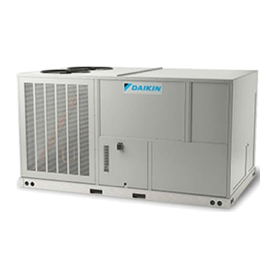
DFG
SERIES
PACKAGED GAS/ELECTRIC UNIT
15 TO 25 T
oN
NOTE: 25 ton model shown in picture.
20 ton model has 4 fans
15 ton model has 3 fans
RECOGNIZE THIS SYMBOL
AS A SAFETY PRECAUTION.
These installation instructions cover the outdoor installation of sin-
gle package heating and cooling units. See the Specification Sheet
applicable to your model for information regarding accessories.
*NOTE: Please contact your distributor or our website for the ap-
plicable Specification Sheet referred to in this manual.
This Forced Air Central Unit Design Complies With Requirements
Embodied in the American National Standard / National Standard
of Canada shown below.
ANSI Z21.47•CSA-2.3 Central Furnaces
© 2022-2023
IOD-1055A
03/2023
Our continuing commitment to quality products may mean a change in specifications without notice.
19001 Kermier Rd. Waller, TX 77484
Only personnel that have been trained to install, adjust,
service, maintenance or repair (hereinafter, "service")
the equipment specified this manual should service the
equipment.
This equipment is not intended for use by persons
(including children) with reduced physical, sensory or
mental capacities, or lack of experience and knowledge,
unless they have been given supervision or instruction
concerning use of the appliance by a person responsible
for their safety.
Children should be supervised to ensure that they do not
play with the equipment.
The manufacturer will not be responsible for any injury
or property damage arising from improper supervision,
service or service procedures. If you service this unit, you
assume responsibility for any injury or property damage
which may result. In addition, in jurisdictions that require
one or more licenses to service the equipment specified in
this manual, only licensed personnel should service the
equipment. Improper supervision, installation, adjustment,
servicing, maintenance or repair of the equipment specified
in this manual, or attempting to install, adjust, service
or repair the equipment specified in this manual without
proper supervision or training may result in product
damage, property damage, personal injury or death.
Do not bypass safety devices.
Safety Instructions ...................................................................2
Replacement Parts ..................................................................2
General Information ................................................................3
Unit Location ...........................................................................4
Clearances ...............................................................................6
Roof Curb Post-Installation Checks...........................................6
Roof Top Duct Connections ......................................................6
Rigging Details .........................................................................7
Electrical Wiring ......................................................................8
Gas Supply Piping ..................................................................10
Propane Gas Installations ......................................................11
Circulating Air and Filters .......................................................12
Venting ..................................................................................13
Condensate Drain Connection ...............................................13
www.daikincomfort.com
INSTALLATION INSTRUCTIONS
WARNING
WARNING
Index
Advertisement
Table of Contents

Related Manuals for Daikin DFG Series


Summary of Contents for Daikin DFG Series
-
Page 1: Table Of Contents
INSTALLATION INSTRUCTIONS SERIES WARNING PACKAGED GAS/ELECTRIC UNIT Only personnel that have been trained to install, adjust, 15 TO 25 T service, maintenance or repair (hereinafter, “service”) the equipment specified this manual should service the equipment. This equipment is not intended for use by persons (including children) with reduced physical, sensory or mental capacities, or lack of experience and knowledge, unless they have been given supervision or instruction... -
Page 2: Safety Instructions
Replacement parts for this appliance are available through your contractor or local distributor. Your nearest distributor can be lo- cated online at www.daikincomfort.com or by contacting: EQUIPMENT SUPPORT DAIKIN COMFORT TECHNOLOGIES MANUFACTURING, L.P. 19001 KERMIER ROAD WALLER, TEXAS 77484 855-770-5678... -
Page 3: General Information
Specification sheets can be found at www.daikincomfort. ASHRAE Handbooks. The manufacturer assumes no responsibility com for Daikin brand products. Within the website, please select for equipment installed in violation of any code or regulation. The the residential or commercial products menu and then select the... -
Page 4: Unit Location
4. File the claim with the following supporting documents: • The flue outlet must be at least 12 inches from any open- ing through which flue gases could enter a building, and a. Original Bill of Lading, certified copy, or indemnity at least three feet above any forced air inlet located with- bond. - Page 5 • This 36” clearance must also be maintained to insure LIFT OVER APPROXIMATE proper combustion air and flue gas flow. The combustion CENTER OF UNIT air intake and furnace flue discharge must not be blocked SPREADER BARS MUST BE USED WITH for any reason, including blockage by snow.
-
Page 6: Clearances
• Ductwork must be constructed using industry guidelines. The duct work must be placed into the roof curb before mounting the package unit. Our full perimeter curbs in- clude duct connection frames to be assembled with the curb. Cantilevered type curbs are not available from the factory. -
Page 7: Rigging Details
RIGGING DETAILS WARNING To prevent property damage, the unit should remain in an upright position during all rigging and moving operations. To facilitate lifting and moving when a crane is used, place the unit in an adequate cable sling. CAUTION Do not lift units two at a time. -
Page 8: Electrical Wiring
For unit protection, use a fuse or HACR circuit breaker that is in CAUTION excess of the circuit ampacity, but less than or equal to the maxi- mum overcurrent protection device. DO NOT EXCEED THE MAXI- MUM OVERCURRENT DEVICE SIZE SHOWN ON UNIT DATA PLATE. To prevent severe damage to the bottom of the unit, do not fork lift unit after wood struts have been removed. - Page 9 Areas Without Convenience Outlet It is recommended that an independent 115V power source be brought to the vicinity of the roof top unit for portable lights and tools used by the service mechanic. NOTE: Refer to local codes for requirements. These outlets can also be factory installed.
-
Page 10: Gas Supply Piping
Piping 4. Route thermostat wires from sub-base terminals to the unit. Control wiring should enter through the duct pan- IMPORTANT NOTE: To avoid possible unsatisfactory operation or el (dimple marks entrance location) or through the ap- equipment damage due to under firing of equipment, do not un- proved base pan location. -
Page 11: Propane Gas Installations
Gas Piping Checks • Listed gas appliance connectors used in accordance with the terms of their listing that are completely in the same room as the equipment CAUTION • In the prior two methods above the connector or tubing must be protected from physical and ther- To prevent property damage or personal injury due to fire, mal damage. -
Page 12: Circulating Air And Filters
3. Pressure drop in lines between regulators, and between a qualified contractor, experienced with natural and pro- second stage regulator and the appliance. Pipe size re- pane gas systems, should attempt conversion. Kit instruc- quired will depend on length of pipe run and total load of tions must be followed closely to assure safe and reliable all appliances. -
Page 13: Venting
VENTING STARTUP, ADJUSTMENTS, AND CHECKS NOTE: Venting is self-contained. WARNING CONDENSATE DRAIN CONNECTION HIGH VOLTAGE To avoid personal injury or death due to Condensate Drain Connection electrical shock, bond the frame of this unit A 1” female NPT drain connection is supplied on the end of the to the building electrical ground by use of the grounding terminal provided or other condensate pan, with an alternative connection on the bottom of... -
Page 14: Air Flow Adjustments
Contractor Responsibility Utilization Voltage - The voltage of the line terminals of the equipment at which the equipment must give fully satisfactory The installing contractor must be certain that: performance. Once it is established that supply voltage will be • All supply and return air ductwork is in place, properly maintained within the utilization range under all system condi- sealed, and corresponds with installation instructions. - Page 15 These wires can be moved together or separately and placed on any unoccupied terminal. NOTE: YL can be moved to tap T3 as long as YL does not share the tap with PU. WH can be moved to tap T7 as long as WH does not share the tap with BR.
-
Page 16: Gas System Check
Electrical Input Check NOTE: Gas appliances located more than 2000 feet above sea lev- el must be derated 4% per 1000 feet of total elevation and that Make preliminary check of evaporator fan ampere draw and veri- variance in gas heating value and specific gravity require change fy that motor nameplate amps are not exceeded. - Page 17 ulator adjustment. In no case should the final manifold pressure MAXIMUM NUMBER GAS ORIFICES MAXIMUM vary more than plus or minus 0.3 inches water column from the INPUT BTUH/BURNER specified nominal pressure. Any major changes in flow should be NATURAL PROPANE (LP) (BTUH) BURNERS...
-
Page 18: Normal Sequence Of Operation - Heating
1. All registers must be open; all duct dampers must be in their final (fully or partially open) position and the unit op- erated for 15 minutes on HIGH FIRE before taking readings. High Fire Regulator 2. The temperature rise must be within the range specified Adjust on the rating plate. -
Page 19: Superheat And Subcooling
9. Integrated ignition control will close its normally open WARNING contacts after a delay of approximately 30 seconds. This action energizes contactor BC and starts the supply fan motor. Operation of the supply fan circulates air across To avoid property damage, personal injury or death due to the heat exchanger and delivers heated air to the condi- fire or explosion, a qualified servicer must investigate the reason for the rollout protection device to open before... -
Page 20: Start-Up Procedure And Checklist
SUPERHEAT = SUCTION LINE TEMP - SAT. SUCTION TEMP. NOTE: Do NOT adjust the charge based on suction pressure unless there is a gross undercharge. If Superheat Adjustment an under charge is suspected recover the charge, re-evacuate the system and recharge per data plate. NOTE: Superheat adjustments should not be made until indoor No adjustments should be made if suspecting a ambient conditions have stabilized. -
Page 21: Normal Sequence Of Operation - Cooling
7.1 Turn power to the unit OFF. 1. Current through primary winding of transformer TRANS1 energizes the 24-volt control circuit. 7.2 Switch any two leads of power supply at unit Single 2. To simulate a mechanical call for cooling from the wall Point Power Block. -
Page 22: Maintenance
MAINTENANCE 10. Check operation of all safety controls. 11. Examine gas furnaces (see below and the User’s Informa- tion Manual). WARNING 12. Check condenser fans and tighten set screws. ELECTRIC SHOCK, FIRE OR EXPLOSION HAZARD Filters Failure to follow safety warnings exactly could result in dangerous operation, serious injury, death or property damage. - Page 23 Do not hit the coil with the hose. We recommend pooling. Daikin recommends a quarterly cleaning of the coils, as placing your thumb over the end of the hose to obtain a the minimum.
-
Page 24: Troubleshooting
Flame Sensor (Qualified Servicer Only) WARNING A drop in the flame current can be caused by a nearly invisible coating on the flame sensor. This coating, created by the fuel or To avoid personal injury or death due to electrical shock, combustion air supply, can be removed by carefully cleaning the do not remove any internal compartment covers or attempt flame sensor with steel wool. - Page 25 The diagnostic fault code is 1 flash for a lockout due to failed igni- Open Thermal Protection Device (4 FLASH CODE) tion attempts or flame dropouts. The integrated control will auto- If the primary limit switch opens, the gas valve is immediately matically reset after one hour, or it can be reset by removing the deenergized, the induced draft and air circulating blowers are en- thermostat signal or disconnecting the electrical power supply for...
-
Page 26: Appendix A Blower Performance Data
APPENDIX A BLOWER PERFORMANCE DATA DIRECT DRIVE - STANDARD DFG1803DL Standard Static DFG1803DM Standard Static Speed Tap Static Airflow RPM 1 RPM 2 BHP 1 BHP 2 Speed Tap Static Airflow RPM 1 RPM 2 BHP 1 BHP 2 3187 0.19 0.16 3187... - Page 27 APPENDIX A BLOWER PERFORMANCE DATA DIRECT DRIVE - STANDARD DFG1803DH Standard Static DFG2403DL Standard Static Speed Tap Static Airflow RPM 1 RPM 2 BHP 1 BHP 2 Speed Tap Static Airflow RPM 1 RPM 2 BHP 1 BHP 2 3187 0.19 0.16 4070...
- Page 28 APPENDIX A BLOWER PERFORMANCE DATA DIRECT DRIVE - STANDARD DFG2403DM Standard Static DFG2403DH Standard Static Speed Tap Static Airflow RPM 1 RPM 2 BHP 1 BHP 2 Speed Tap Static Airflow RPM 1 RPM 2 BHP 1 BHP 2 4070 567.36 513.99 0.33...
- Page 29 APPENDIX A BLOWER PERFORMANCE DATA DIRECT DRIVE - STANDARD DFG3003DL Standard Static DFG3003DM Standard Static Speed Tap Static Airflow RPM 1 RPM 2 BHP 1 BHP 2 Speed Tap Static Airflow RPM 1 RPM 2 BHP 1 BHP 2 5761 705.19 636.84 0.67...
- Page 30 APPENDIX A BLOWER PERFORMANCE DATA DIRECT DRIVE - STANDARD DFG3003DH Standard Static Speed Tap Static Airflow RPM 1 RPM 2 BHP 1 BHP 2 5761 0.67 0.60 5491 0.71 0.65 5161 0.74 0.70 4806 0.78 0.75 4447 0.82 0.79 4092 0.86 0.83 6955...
- Page 31 APPENDIX A BLOWER PERFORMANCE DATA DIRECT DRIVE - HIGH STATIC DFG1803WL High Static Speed Tap Static Airflow RPM 1 RPM 2 BHP 1 BHP 2 Speed Tap Static Airflow RPM 1 RPM 2 BHP 1 BHP 2 6185 0.28 0.26 8228 1.37 1.27...
- Page 32 APPENDIX A BLOWER PERFORMANCE DATA DIRECT DRIVE - HIGH STATIC DFG1803WM High Static Speed Tap Static Airflow RPM 1 RPM 2 BHP 1 BHP 2 Speed Tap Static Airflow RPM 1 RPM 2 BHP 1 BHP 2 6185 0.28 0.26 8958 2.45 2.26...
- Page 33 APPENDIX A BLOWER PERFORMANCE DATA DIRECT DRIVE - HIGH STATIC DFG1803WH High Static Speed Tap Static Airflow RPM 1 RPM 2 BHP 1 BHP 2 Speed Tap Static Airflow RPM 1 RPM 2 BHP 1 BHP 2 6185 0.28 0.26 9745 1063 2.49...
- Page 34 APPENDIX A BLOWER PERFORMANCE DATA DIRECT DRIVE - HIGH STATIC DFG2403WL High Static Speed Tap Static Airflow RPM 1 RPM 2 BHP 1 BHP 2 Speed Tap Static Airflow RPM 1 RPM 2 BHP 1 BHP 2 6244 749.60 675.85 0.82 0.74 6475...
- Page 35 APPENDIX A BLOWER PERFORMANCE DATA DIRECT DRIVE - HIGH STATIC DFG2403WM High Static Speed Tap Static Airflow RPM 1 RPM 2 BHP 1 BHP 2 Speed Tap Static Airflow RPM 1 RPM 2 BHP 1 BHP 2 6244 749.60 675.85 0.82 0.74 9426...
- Page 36 APPENDIX A BLOWER PERFORMANCE DATA DIRECT DRIVE - HIGH STATIC DFG2403WH High Static Speed Tap Static Airflow RPM 1 RPM 2 BHP 1 BHP 2 Speed Tap Static Airflow RPM 1 RPM 2 BHP 1 BHP 2 6244 749.60 675.85 0.82 0.74 9880...
- Page 37 APPENDIX A BLOWER PERFORMANCE DATA DIRECT DRIVE - HIGH STATIC DFG3003WL High Static Speed Tap Static Airflow RPM 1 RPM 2 BHP 1 BHP 2 Speed Tap Static Airflow RPM 1 RPM 2 BHP 1 BHP 2 7461 860.85 773.86 1.28 1.15 7565...
- Page 38 APPENDIX A BLOWER PERFORMANCE DATA DIRECT DRIVE - HIGH STATIC DFG3003WM High Static Speed Tap Static Airflow RPM 1 RPM 2 BHP 1 BHP 2 Speed Tap Static Airflow RPM 1 RPM 2 BHP 1 BHP 2 7461 1.28 1.15 9308 1027 2.25...
- Page 39 APPENDIX A BLOWER PERFORMANCE DATA DIRECT DRIVE - HIGH STATIC DFG3003WH High Static Speed Tap Static Airflow RPM 1 RPM 2 BHP 1 BHP 2 Speed Tap Static Airflow RPM 1 RPM 2 BHP 1 BHP 2 7461 1.28 1.15 9880 1078 2.64...
- Page 40 APPENDIX A BLOWER PERFORMANCE DATA MODELS: DFG3003DL, DFG3004DL, DFG3007DL STANDARD STATIC TO 5HP (0.2 ~1.2 ESP) RPM1 RPM2 DDC% BHP1 BHP2 RPM1 RPM2 DDC% BHP1 BHP2 RPM1 RPM2 DDC% BHP1 BHP2 7000 1.06 0.95 1.20 1.09 1.35 1.23 7500 1.27 1.14 1.42 1.29...
- Page 41 APPENDIX A BLOWER PERFORMANCE DATA MODELS: DFG3003DM, DFG3003DH, DFG3004DM, DFG3004DH, DFG3007DM, DFG3007DH STANDARD STATIC TO 5HP (0.2 ~1.2 ESP) RPM1 RPM2 DDC% BHP1 BHP2 RPM1 RPM2 DDC% BHP1 BHP2 RPM1 RPM2 DDC% BHP1 BHP2 7000 1.06 0.95 1.20 1.09 1.35 1.23 7500 1.27...
- Page 42 APPENDIX A BLOWER PERFORMANCE DATA MODELS: DFC3003D, DFC3004D, DFC3007D STANDARD STATIC TO 5HP (0.2 ~1.2 ESP) RPM1 RPM2 DDC% BHP1 BHP2 RPM1 RPM2 DDC% BHP1 BHP2 RPM1 RPM2 DDC% BHP1 BHP2 7000 0.76 0.75 0.93 0.91 1.13 1.11 7500 0.92 0.89 1.12 1.09...
- Page 43 APPENDIX A ECONOMIZER PRESSURE DROP Airflow Pressure Drop of Downflow Economizer for 15 to 25 Ton Rooftop Units (100% Return Air) SCFM 4500 5000 5500 6000 6500 7000 7500 8000 8500 9000 9500 10000 (In WG) 0.15 0.18 0.22 0.27 0.32 0.37 0.42...
-
Page 44: Appendix B Electrical Data
APPENDIX B ELECTRICAL DATA Optional Powered Optional Power Exhaust Compressor Outdoor Fan Motor Indoor Fan Motor Optional Power Exhaust Power Supply Model Number Electrical Rating Convienience Outlet (Modulating) 84.0/84.0 100/100 88.8/88.8 110/110 13.9 97.9/97.9 110/110 DFG1803D 208/230/3/60 0.33 10.9 9.6/8.7 93.6/92.7 110/110 9.6/8.7... - Page 45 APPENDIX B ELECTRICAL DATA Optional Powered Optional Power Exhaust Compressor Outdoor Fan Motor Indoor Fan Motor Optional Power Exhaust Power Supply Model Number Electrical Rating Convienience Outlet (Modulating) 151/151 175/175 155/155 200/200 13.9 165/165 200/200 DFG3003D 208/230/3/60 48.1 14.5 9.6/8.7 160/159 200/200 9.6/8.7...
-
Page 46: Appendix C Unit Dimensions
APPENDIX C UNIT DIMENSIONS Model 15 Ton 133 - 7/8” 88 - 1/2” 51 - 11/16” 5 - 5/32” 20 Ton 133 - 7/8” 88 - 1/2” 5 - 5/32” 25 Ton NOTE: 15 ton models have 3 fans. 20 ton models have 4 fans 25 ton models have 5 fans 21”... -
Page 47: Appendix D Wiring Diagrams
WIRING DIAGRAMS DFG180* Wiring is subject to change. Always refer to the wiring diagram on the unit for the most up-to-date wiring. - Page 48 WIRING DIAGRAMS DFG180* Wiring is subject to change. Always refer to the wiring diagram on the unit for the most up-to-date wiring.
- Page 49 WIRING DIAGRAMS DFG240* Wiring is subject to change. Always refer to the wiring diagram on the unit for the most up-to-date wiring.
- Page 50 WIRING DIAGRAMS DFG240* Wiring is subject to change. Always refer to the wiring diagram on the unit for the most up-to-date wiring.
- Page 51 WIRING DIAGRAMS DFG300* Wiring is subject to change. Always refer to the wiring diagram on the unit for the most up-to-date wiring.
- Page 52 WIRING DIAGRAMS DFG300* Wiring is subject to change. Always refer to the wiring diagram on the unit for the most up-to-date wiring.
- Page 53 WIRING DIAGRAMS DFG180* DDC Wiring is subject to change. Always refer to the wiring diagram on the unit for the most up-to-date wiring.
- Page 54 WIRING DIAGRAMS DFG180* DDC Wiring is subject to change. Always refer to the wiring diagram on the unit for the most up-to-date wiring.
- Page 55 WIRING DIAGRAMS DFG240* DDC Wiring is subject to change. Always refer to the wiring diagram on the unit for the most up-to-date wiring.
- Page 56 WIRING DIAGRAMS DFG240* DDC Wiring is subject to change. Always refer to the wiring diagram on the unit for the most up-to-date wiring.
- Page 57 WIRING DIAGRAMS DFG300* DDC Wiring is subject to change. Always refer to the wiring diagram on the unit for the most up-to-date wiring.
- Page 58 WIRING DIAGRAMS DFG300* DDC Wiring is subject to change. Always refer to the wiring diagram on the unit for the most up-to-date wiring.
- Page 61 THIS PAGE INTENTIONALLY LEFT BLANK...
- Page 62 THIS PAGE INTENTIONALLY LEFT BLANK...
- Page 63 THIS PAGE INTENTIONALLY LEFT BLANK...
- Page 64 CUSTOMER FEEDBACK Daikin Comfort Technologies is very interested in all product comments. Please fill out the feedback form on the following link: https://daikincomfort.com/contact-us You can also scan the QR code on the right to be directed to the feedback page.
Need help?
Do you have a question about the DFG Series and is the answer not in the manual?
Questions and answers