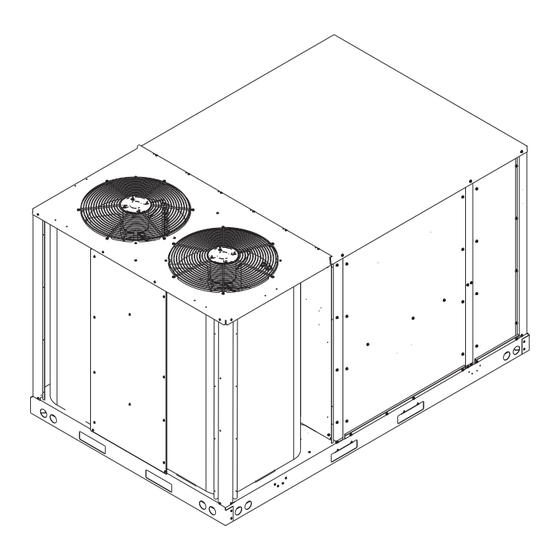
Daikin DFC Series Installation Instructions Manual

Daikin DFC Series Installation Instructions Manual

Light commercial packaged heating and cooling unit 7.5t to 12.5t

Advertisement

Quick Links

DFC/DFH Series Light Commercial Packaged Heating and
Cooling Unit 7.5T to 12.5T
Installation Instructions
Our continuing commitment to quality products may mean a change in specifications without notice.
©2022
IOD-1060A
9/2022
ナンバー :
B150
会社名 :
DAIKIN COMFORT TECHNOLOGIES MANUFACTURING, L.P.
作 成日 :
2022/2/25
19001 Kermier Rd., Waller, TX 77484
ONLY PERSONNEL THAT HAVE BEEN TRAINED TO
INSTALL, ADJUST, SERVICE, MAINTENANCE OR REPAIR
(HEREINAFTER, "SERVICE") THE EQUIPMENT SPECIFIED
IN THIS MANUAL SHOULD SERVICE THE EQUIPMENT. THE
MANUFACTURER WILL NOT BE RESPONSIBLE FOR ANY
INJURY OR PROPERTY DAMAGE ARISING FROM IMPROPER
SERVICE OR SERVICE PROCEDURES. IF YOU SERVICE
THIS UNIT, YOU ASSUME RESPONSIBILITY FOR ANY INJURY
OR PROPERTY DAMAGE WHICH MAY RESULT. IN ADDITION,
IN JURISDICTIONS THAT REQUIRE ONE OR MORE
LICENSES TO SERVICE THE EQUIPMENT SPECIFIED IN THIS
MANUAL, ONLY LICENSED PERSONNEL SHOULD SERVICE
THE EQUIPMENT.
IMPROPER INSTALLATION, ADJUSTMENT, SERVICING,
MAINTENANCE OR REPAIR OF THE EQUIPMENT SPECIFIED
IN THIS MANUAL, OR ATTEMPTING TO INSTALL, ADJUST,
SERVICE OR REPAIR THE EQUIPMENT SPECIFIED IN THIS
MANUAL WITHOUT PROPER TRAINING MAY RESULT IN
PRODUCT DAMAGE, PROPERTY DAMAGE, PERSONAL
INJURY OR DEATH.
DO NOT BYPASS SAFETY DEVICES
www.daikincomfort.com
INSTALLATION INSTRUCTIONS
WARNING
WARNING

Advertisement

Table of Contents
loading

Summary of Contents for Daikin DFC Series

  • Page 1 WARNING DO NOT BYPASS SAFETY DEVICES ナンバー : B150 会社名 : DAIKIN COMFORT TECHNOLOGIES MANUFACTURING, L.P. 作 成日 : 2022/2/25 Our continuing commitment to quality products may mean a change in specifications without notice. ©2022 19001 Kermier Rd., Waller, TX 77484 IOD-1060A www.daikincomfort.com...
  • Page 2: Table Of Contents

    Your nearest distributor present. Failure to do so may cause can be located online at www.daikinac.com or by contacting: property damage, personal injury or death. EQUIPMENT SUPPORT Daikin North America LLC 19001 Kermier Road Waller, Texas 77484 855-770-5678...
  • Page 3: General Information

    Specification sheets can be found at www. refrigeration tonnage, heating input and voltage. daikinac.com for Daikin brand products. Within the website, please select the residential or commercial products menu Carefully inspect the unit for damage including damage and then select the submenu for the type of product to be to the cabinetry.
  • Page 4 • To avoid possible personal injury, a safe, flat surface for service personnel should be provided. WARNING • As indicated on the unit data plate, a minimum clearance of 36" to any combustible material is To prevent possible equipment damage, property required on the furnace access side of the unit.
  • Page 5: Clearances

    • Sufficient structural support must be determined prior there should be a minimum of 48” clearance and provisions to locating and mounting the curb and package unit. made to deflect the warm discharge air out from the • Ductwork must be constructed using industry overhang.
  • Page 6: Rigging Details

    recommended. Insulate and weatherproof all external • Lifting cables should be attached to the unit with ductwork and joints as required and in accordance with shackles. local codes. • The distance between the crane hook and the top of the unit must not be less than 60". •...
  • Page 7: Weights And Center Of Gravity

    Important: If using bottom discharge with roof NOTE: Unit should be lifted at a point above curb, ductwork should be attached to the curb center of gravity. prior to installing the unit. Ductwork dimensions are shown in Roof Curb Installation Instructions. DFC Weights (lbs) Data Refer to the Roof Curb Installation Instructions for proper...
  • Page 8: Electrical Wiring

    Electrical Code (ANSI/NFPA 70), and all local codes and Remove spreader bars, lifting cables and other rigging ordinances. equipment. The main power supply shall be three-phase, three wire. ELECTRICAL WIRING The unit is factory wired for the voltage shown on the unit’s data plate.
  • Page 9 NOTE: Refer to local codes for requirements. These outlets can also be factory installed. Units installed on Roof Tops Main power and low voltage wiring may enter the unit HIGH VOLTAGE BLOCK through the condenser end of unit or through the roof curb.
  • Page 10: Circulating Air And Filters

    Low Voltage Control Wiring 1. A 24V thermostat must be installed for unit operation. 2. Locate thermostat or remote sensor in the conditioned space where it will sense average temperature. Do not locate the device where it may be directly exposed to supply air, sunlight or other sources of heat.
  • Page 11: Startup, Adjustments, And Checks

    STARTUP, ADJUSTMENTS, AND CHECKS Temporary Heating Or Cooling If the unit is to be used for temporary heating or cooling, Pre-Startup Instructions - General a “Startup, Adjustments, and Checks" must first be Prior to the beginning of Startup, Adjustment, and Checks performed in accordance with this manual.
  • Page 12: Air Flow Adjustments

    System Voltage - The nominal voltage value assigned to a circuit or system for the purpose of designating its voltage class. Nameplate Voltage - The voltage assigned to a piece of equipment for the purpose of designating its voltage class and for the purpose of defining the minimum and maximum voltage at which the equipment will operate.
  • Page 13 BLOWER SPEED SELECTION These wires can be moved together or separately and The unit has one set of taps for cooling (T1-T5) , taps for placed on any unoccupied terminal. heatpump (T3-T5) and a second set of taps for electric heater heating - (E.Heat) (T6-T10).
  • Page 14 Set Evaporator Fan Rpm Actual RPM’s must be set and verified with a tachometer Heat Pump Start-Up Procedure or strobe light. Refer to Appendex A for basic unit fan 1. Check the cooling mode for the heat pump in the RPM.
  • Page 15 Y2 and between R and G on TB1 terminal block will 2. To simulate a mechanical call for cooling from the wall simulate a satisfied thermostat. The compressors thermostat, place a jumper across terminals R and Y1 will cycle off and IIC (pin 12) will initiate its time delay of terminal block TB1.
  • Page 16 To obtain the amount of subcooling, subtract 1. Purge gauge lines. Connect service gauge manifold 109°F from 120°F. The difference is 11° subcooling. to access fittings. Run system at least 15 minutes to allow pressure to stabilize. See the specification sheet or technical 2.
  • Page 17: Heat Pump Operation

    cycle) where the heat is removed, and the vapor When the heat pump is on the heating cycle, the outdoor condenses to liquid. It then goes through the expansion coil is functioning as an evaporator. The temperature device to the outdoor coil (condenser on the cooling cycle) of the refrigerant in the outdoor coil must be below where the liquid is evaporated, and the vapor goes to the the temperature of the outdoor air in order to extract...
  • Page 18: Maintenance

    MAINTENANCE 4. Check for blockage of condensate drain. 5. Check power and control voltages. 6. Check running amperage. WARNING 7. Check operating temperatures and pressures. 8. Check and adjust temperature and pressure controls. 9. Check and adjust damper linkages. ELECTRICAL SHOCK, FIRE OR EXPLOSION HAZARD 10.
  • Page 19: Troubleshooting

    is on the cooling cycle, raise the discharge pressure Functional Parts by restricting airflow through the outdoor coil. If the Refer to the unit Parts Catalog for a list of functional parts. valve does not shift after the above attempts, cut Parts are available from your distributor.
  • Page 20 DFH OPERATIONS WIRE RANGE HEAT PUMP Y1 Y2 W1 W2 O DH T1 T9 T10 Fan Only Cooling Mode LO Cooling Mode HI Mech. Heating Mode LO Mech. Heating Mode HI Elec. Heating Mode LO Elec. Heating Mode HI Mech. Plus Elec. Heat W1 X Mech.
  • Page 21: Appendix A Blower Performance Data

    APPENDIX A BLOWER PERFORMANCE DATA 7.5 TON AC 7.5T AC Standard Static Motor 2.4 HP Model: DFC090_STD DOWNSHOT HORIZONTAL TAP SPEED SCFM R.P.M. WATTS TAP SPEED SCFM R.P.M. WATTS 1927.5 436.1 136.1 0.20 1951.6 453.2 143.7 0.21 1749.5 518.0 169.5 0.24 1843.9 526.3...
  • Page 22 APPENDIX A BLOWER PERFORMANCE DATA 7.5 TON AC 7.5T AC Medium Static Motor 2.4 HP Model: DFC090_MED DOWNSHOT HORIZONTAL TAP SPEED SCFM R.P.M. WATTS TAP SPEED SCFM R.P.M. WATTS 2090.0 455.6 173.6 0.26 2106.3 475.5 183.8 0.27 1918.8 533.7 207.0 0.30 1998.1 545.1...
  • Page 23 APPENDIX A BLOWER PERFORMANCE DATA 7.5 TON AC 7.5T AC High Static Motor 2.4 HP Model: DFC090_HIGH DOWNSHOT HORIZONTAL TAP SPEED SCFM R.P.M. WATTS TAP SPEED SCFM R.P.M. WATTS 2402.9 493.3 251.0 0.37 2404.3 518.5 266.6 0.39 2244.2 564.3 284.6 0.42 2295.7 581.7...
  • Page 24 APPENDIX A BLOWER PERFORMANCE DATA 8.5 TON AC 8.5T AC Standard Static Motor 2.4 HP Model: DFC102_STD DOWNSHOT HORIZONTAL TAP SPEED SCFM R.P.M. WATTS TAP SPEED SCFM R.P.M. WATTS 2090.0 455.6 173.6 0.26 2106.3 475.5 183.8 0.27 1918.8 533.7 207.0 0.30 1998.1 545.1...
  • Page 25 APPENDIX A BLOWER PERFORMANCE DATA 8.5 TON AC 8.5T AC Medium Static Motor 2.4 HP Model: DFC102_MED DOWNSHOT HORIZONTAL TAP SPEED SCFM R.P.M. WATTS TAP SPEED SCFM R.P.M. WATTS 2209.2 470.0 202.3 0.30 2219.8 491.9 214.4 0.31 2042.8 545.3 235.7 0.35 2111.4 559.0...
  • Page 26 APPENDIX A BLOWER PERFORMANCE DATA 8.5 TON AC 8.5T AC High Static Motor 2.4 HP Model: DFC102_HIGH DOWNSHOT HORIZONTAL TAP SPEED SCFM R.P.M. WATTS TAP SPEED SCFM R.P.M. WATTS 2349.3 486.8 237.2 0.35 2353.2 511.1 251.9 0.37 2188.5 559.0 270.8 0.40 2244.6 575.4...
  • Page 27 APPENDIX A BLOWER PERFORMANCE DATA 10 TON AC 10T AC Standard Static Motor 2.4 HP Model: DFC120_STD DOWNSHOT HORIZONTAL TAP SPEED SCFM R.P.M. WATTS TAP SPEED SCFM R.P.M. WATTS 2154.1 434.4 172.3 0.24 2099.0 439.9 228.0 0.24 PL Rated TAP 1 PL Rated TAP 1 TAP SPEED...
  • Page 28 APPENDIX A BLOWER PERFORMANCE DATA 10 TON AC 10T AC Medium Static Motor 3.5 HP Model: DFC120_MED DOWNSHOT HORIZONTAL TAP SPEED SCFM R.P.M. WATTS TAP SPEED SCFM R.P.M. WATTS 2471.3 466.7 232.0 0.34 2397.2 474.9 269.3 0.34 2292.9 546.0 268.3 0.40 2148.1 577.7...
  • Page 29 APPENDIX A BLOWER PERFORMANCE DATA 10 TON AC 10T AC High Static Motor 3.5 HP Model: DFC120_HIGH DOWNSHOT HORIZONTAL TAP SPEED SCFM R.P.M. WATTS TAP SPEED SCFM R.P.M. WATTS 2586.6 478.5 255.7 0.38 2505.5 487.7 287.0 0.39 2415.4 556.0 293.8 0.44 2273.9 584.6...
  • Page 30 APPENDIX A BLOWER PERFORMANCE DATA 12.5 TON AC 12.5T AC Standard Static Motor 3.5 HP Model: DFC150_STD DOWNSHOT HORIZONTAL TAP SPEED SCFM R.P.M. WATTS TAP SPEED SCFM R.P.M. WATTS 2158.1 453.9 184.5 0.25 2123.9 462.4 190.2 0.26 1860.0 565.3 228.4 0.31 1926.4 534.1...
  • Page 31 APPENDIX A BLOWER PERFORMANCE DATA 12.5 TON AC 12.5T AC Medium Static Motor 5 HP Model: DFC150_MED DOWNSHOT HORIZONTAL TAP SPEED SCFM R.P.M. WATTS TAP SPEED SCFM R.P.M. WATTS 2542.9 482.5 250.6 0.39 2459.6 510.2 266.8 0.41 2344.0 560.9 287.8 0.45 2227.6 602.4...
  • Page 32 APPENDIX A BLOWER PERFORMANCE DATA 12.5 TON AC 12.5T AC High Static Motor 5 HP Model: DFC150_HIGH DOWNSHOT HORIZONTAL TAP SPEED SCFM R.P.M. WATTS TAP SPEED SCFM R.P.M. WATTS 2752.1 506.0 312.9 0.47 2659.3 536.5 334.4 0.49 2562.0 580.5 352.1 0.53 PL Rated TAP 1...
  • Page 33 APPENDIX A BLOWER PERFORMANCE DATA 7.5 TON HP 7.5T Heat Pump Standard Static 7.5T Heat Pump Standard Static Horizontal Models: DFH0903D, DFH0904D, DFH0907D Models: DFH0903D, DFH0904D, DFH0907D TAP SPEED SCFM R.P.M. WATTS TAP SPEED SCFM R.P.M. WATTS 1974.0 437.7 196.2 0.23 1928.0 448.7...
  • Page 34 APPENDIX A BLOWER PERFORMANCE DATA 7.5 TON HP 7.5T Heat Pump Medium Static Downshot 7.5T Heat Pump Medium Static Horizontal Models: DFH0903L, DFH0904L, DFH0907L Models: DFH0903L, DFH0904L, DFH0907L TAP SPEED SCFM R.P.M. WATTS TAP SPEED SCFM R.P.M. WATTS 2298.0 473.0 255.6 0.33 2284.0...
  • Page 35 APPENDIX A BLOWER PERFORMANCE DATA 7.5 TON HP 7.5T Heat Pump High Static Downshot 7.5T Heat Pump High Static Horizontal Models: DFH0903W, DFH0904W, DFH0907W Models: DFH0903W, DFH0904W, DFH0907W Tap Speed SCFM R.P.M. WATTS TAP SPEED SCFM R.P.M. WATTS 2465.0 489.8 281.4 0.36 2368.0...
  • Page 36 APPENDIX A BLOWER PERFORMANCE DATA 8.5 TON HP 8.5T Heat Pump Standard Static Downshot 8.5T Heat Pump Standard Static Horizontal Models: DFH1023D, DFH1024D, DFH1027D Models: DFH1023D, DFH1024D, DFH1027D TAP SPEED SCFM R.P.M. WATTS TAP SPEED SCFM R.P.M. WATTS 1974.0 437.7 196.2 0.23 1928.0...
  • Page 37 APPENDIX A BLOWER PERFORMANCE DATA 8.5 TON HP 8.5T Heat Pump Medium Static Downshot 8.5T Heat Pump Medium Static Horizontal Models: DFH1023L, DFH1024L, DFH1027L Models: DFH1023L, DFH1024L, DFH1027L TAP SPEED SCFM R.P.M. WATTS TAP SPEED SCFM R.P.M. WATTS 2298.0 473.0 255.6 0.33 2284.0...
  • Page 38 APPENDIX A BLOWER PERFORMANCE DATA 8.5 TON HP 8.5T Heat Pump High Static Downshot 8.5T Heat Pump High Static Static Horizontal Models: DFH1023W, DFH1024W, DFH1027W Models: DFH1023W, DFH1024W, DFH1027W Tap Speed SCFM R.P.M. WATTS TAP SPEED SCFM R.P.M. WATTS 2465.0 489.8 281.4 0.36...
  • Page 39 APPENDIX A BLOWER PERFORMANCE DATA 10 TON HP 10T Heat Pump Standard Static Downshot 10T Heat Pump Standard Static Downshot Models: DFH1203D, DFH1203D, DFH1203D Models: DFH1203D, DFH1203D, DFH1203D TAP SPEED SCFM R.P.M. WATTS TAP SPEED SCFM R.P.M. WATTS 2356.0 465.7 211.5 2308.0 468.9...
  • Page 40 APPENDIX A BLOWER PERFORMANCE DATA 10 TON HP 10T Heat Pump Medium Static Downshot 10T Heat Pump Medium Static Horizontal Models: DFH1203L, DFH1204L, DFH1207L Models: DFH1203L, DFH1204L, DFH1207L TAP SPEED SCFM R.P.M. WATTS Speed Tap R.P.M. WATTS 2452.0 481.1 242.1 0.35 0.20 2457.0...
  • Page 41 APPENDIX A BLOWER PERFORMANCE DATA 10 TON HP 10T Heat Pump High Static Downshot 10T Heat Pump High Static Horizontal Models: DFH1203W, DFH1204W, DFH1207W Models: DFH1203W, DFH1204W, DFH1207W TAP SPEED SCFM R.P.M. WATTS TAP SPEED SCFM R.P.M. WATTS 2682.0 503.6 266.6 0.45 2701.0...
  • Page 42: Appendix B Electrical Data

    APPENDIX B ELECTRICAL DATA Electrical Data Optional Powered Optional Power Electrical Compressor Outdoor Fan Motor Indoor Fan Motor Optional Electric Heat Power Supply Convienience Exhaust Model Number Rating Type Part # 41.6/41.6 50/50 9.6/8.7 51.2/50.3 60/60 3.3/3.0 44.9/44.6 50/50 9.6/8.7 3.3/3.0 54.5/53.3 60/60...
  • Page 43 APPENDIX B ELECTRICAL DATA Electrical Data Optional Powered Optional Power Electrical Compressor Outdoor Fan Motor Indoor Fan Motor Optional Electric Heat Power Supply Convienience Exhaust Model Number Rating Type Part # 15.1 18.6 16.3 19.8 23.0 27.4 EH*D-7M15 14.4 Direct 24.5 Drive 28.9...
  • Page 44 APPENDIX B ELECTRICAL DATA Electrical Data Optional Powered Optional Power Electrical Compressor Outdoor Fan Motor Indoor Fan Motor Optional Electric Heat Power Supply Model Number Convienience Exhaust Rating Type Part # 21.4 25.7 22.4 26.7 29.3 34.7 EH*D-4M15 Direct 30.6 Drive 35.9 DFC1024D...
  • Page 45 APPENDIX B ELECTRICAL DATA Electrical Data Optional Powered Optional Power Electrical Compressor Outdoor Fan Motor Indoor Fan Motor Optional Electric Heat Power Supply Model Number Convienience Exhaust Rating Type Part # 47.2/47.2 60/60 9.6/8.7 56.8/55.9 70/70 3.3/3.0 50.5/50.2 60/60 9.6/8.7 3.3/3.0 60.1/58.9 70/70...
  • Page 46 APPENDIX B ELECTRICAL DATA Electrical Data Optional Powered Optional Power Compressor Outdoor Fan Motor Indoor Fan Motor Optional Electric Heat Power Supply Electrical Model Number Convienience Exhaust Rating Type Part # 18.5 22.0 19.7 23.2 23.0 27.4 EH*D-7M15 14.4 Direct 24.5 Drive 28.9...
  • Page 47 APPENDIX B ELECTRICAL DATA Electrical Data Optional Powered Optional Power Compressor Outdoor Fan Motor Indoor Fan Motor Optional Electric Heat Power Supply Electrical Model Number Convienience Exhaust Rating Type Part # 31.9 36.2 32.9 37.2 31.9 36.9 EH*D-4M15 Direct 32.9 Drive 38.2 DFC1504D...
  • Page 48 APPENDIX B ELECTRICAL DATA Electrical Data Optional Optional Power Electrical Compressor Outdoor Fan Motor Indoor Fan Motor Optional Electric Heat Power Supply Model Number Powered Exhaust Rating Type Part # 41.6/41.6 50/50 9.6/8.7 51.2/50.3 60/60 3.3/3.0 44.9/44.6 50/50 9.6/8.7 3.3/3.0 54.5/53.3 60/60 80.7/86.7...
  • Page 49 APPENDIX B ELECTRICAL DATA Electrical Data Optional Optional Power Electrical Compressor Outdoor Fan Motor Indoor Fan Motor Optional Electric Heat Power Supply Model Number Powered Exhaust Rating Type Part # 15.1 18.6 16.3 19.8 33.2 36.7 EH*D-7M15 14.4 Direct 34.4 Drive 37.9 DFH0907D...
  • Page 50 APPENDIX B ELECTRICAL DATA Electrical Data Optional Optional Power Electrical Compressor Outdoor Fan Motor Indoor Fan Motor Optional Electric Heat Power Supply Model Number Powered Exhaust Rating Type Part # 23.0 27.3 24.0 28.3 45.5 49.8 EH*D-4M15 Direct 46.5 Drive 50.8 DFH1024D 460/3/60...
  • Page 51 APPENDIX B ELECTRICAL DATA Electrical Data Optional Optional Power Electrical Compressor Outdoor Fan Motor Indoor Fan Motor Optional Electric Heat Power Supply Model Number Powered Exhaust Rating Type Part # 51.5/51.5 60/60 9.6/8.7 61.1/60.2 70/70 3.3/3.0 54.8/54.5 70/70 9.6/8.7 3.3/3.0 64.4/63.2 80/70 90.6/96.6 100/100...
  • Page 52 APPENDIX B ELECTRICAL DATA Electrical Data Optional Optional Power Compressor Outdoor Fan Motor Indoor Fan Motor Optional Electric Heat Power Supply Electrical Model Number Powered Exhaust Rating Type Part # 20.1 23.6 21.3 24.8 38.2 41.7 EH*D-7M15 14.4 Direct 39.4 Drive 42.9 DFH1207D...
  • Page 53: Appendix C Unit Dimensions

    APPENDIX C UNIT DIMENSIONS 60-3/16" 90-5/8" Models Dimension "A" in. DFC090-150 54-5/8 DFH090-120 54-5/8 54-5/8" 4-1/4" 90-3/4" 60-3/8" Figure 14 1" 13" RETURN 12.5" X 36.4" SUPPLY 13.9" X 28.3" 9-1/2" Horizontal Discharge Figure 13 19-11/16 NOTE NOTE For horizontal discharge, remove supply and return For horizontal discharge, remove supply and return 6-5/8 RETURN...
  • Page 54: Appendix D Min-Max Airflow

    APPENDIX D MIN-MAX AIRFLOW AIR FLOW FOR ELECTRIC HEAT HEATER KIT MODEL NUMBER NOMENCLATURE HEATER KIT 6, 7 MINIMUM MAXIMUM UNIT MODEL NUMBER Electric EH*D-*M15 2400 4225 EH*D-*M30 Heater EH*D-*M45 Staged EH*D-*M15 SCR (modulating) 2750 4425 EH*D-*M30 Drive System EH*D-*M45 Belt Drive EH*D-*M15 Direct Drive...
  • Page 55: Wiring Diagram

    WIRING DIAGRAM Wiring is subject to change. Always refer to the wiring diagram on the unit for the most up-to-date wiring.
  • Page 56 WIRING DIAGRAM Wiring is subject to change. Always refer to the wiring diagram on the unit for the most up-to-date wiring.
  • Page 57: Start-Up Checklist

    DAIKIN Start-up Checklist *Store in job file Date: Location: Model Number: Serial Number: Technician: Unit#: Pre Start-Up (Check each item as completed) Verify all packaging material has been removed. Remove all shipping brackets per installation instructions. Verify the job site voltage agrees with the unit serial plate.
  • Page 59 PAGE LEFT INTENTIONALLY BLANK...
  • Page 60 CUSTOMER FEEDBACK Daikin is very interested in all product comments. Please fill out the feedback form on the following link: https://daikincomfort.com/contact-us You can also scan the QR code on the right to be directed to the feedback page. ナンバー :...

Table of Contents