
Related Manuals for Kichler Lighting Decor Dorset


Summary of Contents for Kichler Lighting Decor Dorset
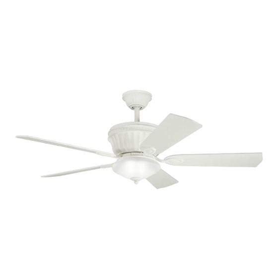
- Page 1 Dorset ® ™ A Kichler Decor ceiling fan Kichler ® Lighting 7711 East Pleasant Valley Road P.O. Box 318010 Instruction Manual Cleveland, Ohio 44131-8010 Customer Service 866.558.5706 8:30 AM to 5:00 PM EST, Monday - Friday...
-
Page 2: Safety Rules
1. SAFETY RULES 1. To reduce the risk of electric shock, insure 10. Do not use water or detergents when electricity has been turned off at the circuit cleaning the fan or fan blades. A dry dust breaker or fuse box before beginning. cloth or lightly dampened cloth will be suitable for most cleaning. -
Page 3: Tools And Materials Required
Dorset 2. TOOLS AND MATERIALS REQUIRED Philips screw driver Blade screw driver 11 mm wrench Step ladder Wire cutters 3. PACKAGE CONTENTS Unpack your fan and check the contents. You should have the following items: Fan blades (5) Ceiling mounting plate Motor and hanger plate assembly Motor housing Set of 5 blade brackets and Pre-Installed... -
Page 4: Mounting Options
4. MOUNTING OPTIONS If there isn't an existing UL (cUL for Canadian Installation) listed mounting box, then read the following instructions. Disconnect the power by removing fuses or turning off circuit breakers. Secure the outlet box directly to the building structure. -
Page 5: Hanging The Fan
Dorset 5. HANGING THE FAN CUL Listed REMEMBER to turn off the power before you electrial box begin. Ceiling mounting plate To properly install your ceiling fan, follow the steps below. Washers Step 1. Secure the ceiling mounting Plate to Mounting screws the ceiling outlet box using screws and Fig. -
Page 6: Electrical Connections
7. ELECTRICAL CONNECTIONS WARNING: To avoid possible electrical shock, Outlet box be sure you have turned off the power at the White (neutral) main circuit panel. Black (hot) Follow the steps below to connect the fan to Green or bare copper (ground) Black ("AC IN L") your household wiring. - Page 7 Dorset Note: Fan must be installed at a maximum distance of 30 feet from the CoolTouch™ Remote Transmitter for optimal signal transmission between the transmitter and the Code switch fan's receiving unit. For best performance, make sure the Black Antenna, on the end of the receiver, remains extended and not tangled with any of the electrical wires.
-
Page 8: Finishing The Fan Installation
8. FINISHING THE INSTALLATION 1. Remove the four sets of nuts and washers located on the mounting plate threaded studs. Mounting Plate threaded 2. Place the control receiver between the studs mounting bracket and the ceiling mounting Mounting Receiver plate with all of the wiring connection made plate in the previous step. -
Page 9: Attaching The Fan Blades
Dorset 10. ATTACHING THE FAN BLADES Step 1. Place a blade on a blade bracket aligning the mounting holes on each. Start each set of mounting screws, washers and fiber pads into each hole. Make sure the blade is straight on the blade bracket and tighten each mounting screw until Screws the fiber pad is slightly compressed. -
Page 10: Installing The Light Fixture
12. INSTALLING THE LIGHT FIXTURE NOTE: Before continuing installation, confirm that the power is still turning off at the main circuit breaker or by removing the correct fuse. Turning the power off using a wall switch is not sufficient to prevent electrical shock. 1. - Page 11 Dorset 13. INSTALLING THE LAMPS AND GLASS SHADE 1. Install 3, E-12 40 Watt T-3 Krypton lamps (provided). (Fig. 15) 2. Remove the metal nut, glass cap and decorative nut from the light fixture stem. Place the glass shade over the light fixture stem and secure with the metal nut (rubber side on against the glass).
-
Page 12: Installing The Batteries
14. INSTALLING THE BATTERIES Remove the battery compartment cover on the back of the CoolTouch™ Transmitter and insert both batteries provided. Make sure the + sign is facing up. Take care during this procedure NOT TO move the frequency dip switches inside this compartment. - Page 13 Dorset Speed settings for warm or cool weather depend on factors such as the room size. Ceiling height, number of fans and so on. Warm Weather Operation: Forward (counter clockwise) A downward airflow creates a cooling effect as shown in Fig. 18. This allows you to set your air conditioner on a warmer setting without affecting your general comfort.
-
Page 14: Installing The Cooltouch Control System Wall Plate
16. INSTALLING THE COOLTOUCH ™ CONTROL SYSTEM WALL PLATE Outlet box Switch Select a location to install your CoolTouch™ Wall plate Control System Transmitter. You can replace an existing wall switch or, install the transmitter on ANY flat surface. Option 1: Install the control system using an existing wall switch outlet box. -
Page 15: Troubleshooting
Dorset 18. TROUBLESHOOTING Problem Solution Fan will not start. 1. Check circuit fuses or breakers. 2. Check all electrical connections to insure proper contact. CAUTION: Make sure the main power is OFF when checking any electrical connection. 3. Make sure the batteries are installed properly. Positive (+) side facing out. 4.
Need help?
Do you have a question about the Decor Dorset and is the answer not in the manual?
Questions and answers