Table of Contents
Advertisement
Quick Links
Kichler
Lighting
®
7711 East Pleasant Valley Road
P.O. Box 318010
Cleveland, Ohio 44131-8010
Customer Service
866.558.5706
8:30 AM to 5:00 PM EST,
Monday - Friday
Includes our new
CoolTouch Control System
TM
Looks permanent, but goes wherever you go!
U.S. Patent Pending
Instruction Manual
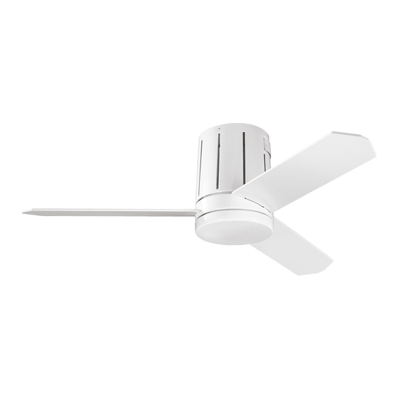
Innes
II
TM
300130
A Kichler
Decor
ceiling fan
®
™
3066708
Advertisement
Table of Contents

Subscribe to Our Youtube Channel
Related Manuals for Kichler Lighting Decor InnesII 300130


Summary of Contents for Kichler Lighting Decor InnesII 300130
- Page 1 Innes II 300130 A Kichler Decor ceiling fan ® ™ Includes our new CoolTouch Control System Looks permanent, but goes wherever you go! U.S. Patent Pending Kichler Lighting ® 7711 East Pleasant Valley Road P.O. Box 318010 Instruction Manual Cleveland, Ohio 44131-8010 Customer Service 866.558.5706 8:30 AM to 5:00 PM EST,...
-
Page 2: Safety Rules
1. SAFETY RULES 1. To reduce the risk of electric shock, insure 10. Do not use water or detergents when electricity has been turned off at the circuit cleaning the fan or fan blades. A dry dust breaker or fuse box before beginning. cloth or lightly dampened cloth will be suitable for most cleaning. -
Page 3: Tools And Materials Required
InnesI I 2. TOOLS AND MATERIALS REQUIRED Philips screw driver Blade screw driver 11 mm wrench Step ladder Wire cutters 3. PACKAGE CONTENTS Unpack your fan and check the contents . You should have the following items: Top Housing Motor Body Flywheel Blade (3) Switch Housing... -
Page 4: Mounting Options
4. MOUNTING OPTIONS If there isn't an existing ETL listed mounting box, then read the following instructions. Disconnect the power by removing fuses or turning off circuit breakers. Secure the outlet box directly to the building structure. Use appropriate fasteners and Outlet box building materials. -
Page 5: Hanging The Fan
InnesI I 5. HANGING THE FAN REMEMBER to turn off the power before you begin installation. This is necessary for your safety and also the proper programming of the control system. To properly install your ceiling fan, follow the steps below. Mounting Bracket Screw Step 1. - Page 6 6. INSTALLATION THE SAFETY SUPPORT A safety support cable is provided to help prevent Flat Washer the ceiling fan from failing, please install it as Wood Screw follows. Support Brace Spring Washer Step 1. Drive a wood screw and washers into the Ceiling Outlet Box side of the brace that holds the outlet box.
-
Page 7: Finishing The Installation
InnesI I Step 1. Motor to Receiver Electrical Connections: Connect the BLACK wire from the fan to BLACK wire marked "TO MOTOT L" from the receiver. Connect the WHITE wire from the fan to the WHITE wire marked "TO MOTOR N" from the receiver. - Page 8 Motor Body Step 2. Assemble the top housing onto the motor body using the three screws provided in the hardware bag and securely tighten. (Fig. 13) Screw Top Housing Receiver Door NOTE: Please let the receiver door face up Fig. 13 the notch on the motor body for receiver replacement.
- Page 9 InnesI I Step 5. Remove one of the three screws in the mounting plate. Slightly loosen the remaining two screws. Assemble the switch housing to the mounting plate using the two key slots. Mounting Plate Switch Housing Replace the third screw and securely tighten all three screws.
- Page 10 9. HOW TO REPLACE THE RECEIVER Receiver Door Step 1. Remove the two screws and receiver door in the motor body. Retain them for installatio step 4. (Fig. 20) Screw Motor Body Fig. 20 Receiver Step 2. Pull out the steel plate from the motor body and loosen the wire connectors of receiver.
-
Page 11: Installing The Transmitter
InnesI I 10. INSTALLING THE COOLTOUCH CONTROL SYSTEM WALL PLATE Outlet Box Select a location to install your CoolTouch Switch Control System Transmitter. You can replace Wall Plate an existing wall switch, or install the transmitter on ANY flat surface. Option 1: Install the control system using an existing wall switch outlet box. -
Page 12: Control System Set-Up
12. CONTROL SYSTEM SET-UP NOTE: Make sure the power is completely disconnected before you begin this procedure. Read all of these steps before preceeding. Each step must be followed exactly to properly program the control system. Step 1. Install 2,3 volt # 2032 battery included with the CoolTouch TM Control system and CHLER 2032... - Page 13 InnesI I 13. OPERATING INSTRUCTIONS: Restore power to ceiling fan and test for Speed Buttons proper operation. Figure 29 1. Buttons These three buttons are used to set the fan Forward/Reverse Button speed as follows: = Low Speed = Medium Speed = High Speed 2.
-
Page 14: Troubleshooting
14. TROUBLESHOOTING Problem Solution Fan will not start. 1. Check circuit fuses or breakers. 2. Check all electrical connections to insure proper contact. CAUTION: Make sure the main power is OFF when checking any electrical connection. 3. Make sure the transmitter batteries are installed properly. Positive (+) side facing out.
Need help?
Do you have a question about the Decor InnesII 300130 and is the answer not in the manual?
Questions and answers