Table of Contents
Advertisement
Quick Links
Advertisement
Table of Contents

Related Manuals for AnyTone ARES II


Summary of Contents for AnyTone ARES II
- Page 1 Qixiang Electron Science & Technology Co.,Ltd. www.anytone.net...
- Page 2 ARES II Instruction Manual...
-
Page 4: Table Of Contents
CONTENTS FUNCTIONS & FEATURES ..............1 STANDARD ACCESSORIE ..............2 OPTIONAL ACCESSORIE ..............2 INSTALLATION ..................2 GETTING ACQUAINTED ..............6 HOW TO USE YOUR RADIO ...............8 SLIDE SWTICH ..................9 FUNCTION MENU ................10 ERROR CODE ..................11 SPECIFICATIONS ................11... -
Page 5: Functions & Features
FUNCTIONS & FEATURES ◆ PA/FM/AM/USB/LSB mode ◆ Weather Channel 150-170MHz programmable(Optional) ◆ CTCSS/DCS Code ◆ PWR, RX RSSI S-Meter ◆ PC programmable ◆ Echo Function ◆ SQ, ASQ Function ◆ RF Gain Adjustment ◆ Mike Gain Adjustment ◆ RF PWR Adjustment ◆... -
Page 6: Standard Accessorie
STANDARD ACCESSORIES Radio Microphone Mounting Bracket Microphone Non-slip Hanger DC Power Screws for Pads for Adjusting Spare Fuses Self-tapping Pads Cable bracket bracket screws Screws (10A,250V) OPTIONAL ACCESSORIE USB Programming External Speaker Cable INSTALLLATON Choose the most appropriate setting from a simple and practical point of view. -
Page 7: Installation
Microphone connection 1. Plug microphone connector into jack. 2. Pull on the screw for microphone connector. ANTENNA INSTALLATION Before using this radio, please install a high efficent and harmonious adjusted CB antenna, suitable antenna type and correct installation will bring excellent communication. - Page 8 1. Connect positive red power cable with the + terminal of the battery. 2. Connect negative black power cable with the - terminal of the battery. 3. Connect the DC power cable to the transceiver's power supply connector. ▲ We suggest not use cigar lighter as it often bring down the voltage. ▲...
- Page 9 Install Microphone Hanger Choose a ideal location which will not interfere the driver. Using supplied self-tapping screws and pads(2 sets) to fix the hanger. Install External Speaker If use an external speaker, please choose 8ohm speaker with 3.50mm mono band (doulbe cable) plug.
-
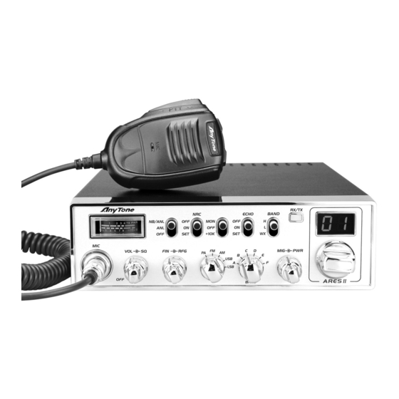
Page 10: Getting Acquainted
GETTING ACQUAINTED Front Panel No. Functions S-Meter Control NB/ANL function on/off NRC◆function◆on/off◆/set Control Monitor/10K on/off ECHO◆function◆on/off◆/set Choose H and L band group TX/RX indicator Channnel display Mike connector Power on/off volume level control Squelch level control SSB frequency FINE function Control RF gain level Choose PA/FM/AM/USB/LSB mode Choose working band... - Page 11 Rear Panel 21 20 19 ANT. PA.SP. EXT.SP. POWER Functions External SP Jack PC programming port External PA Jack Antenna Jack Power Supply Jack Microphone Channel Down Channel UP Connector Microphone cable...
-
Page 12: How To Use Your Radio
HOW TO USE YOUR RADIO OFF/ON Radio 1. Turn VOL clockwise to switch on the radio, the radio emit a beep. When the LED displays frequency or channel, the radio is on. 2. Turn VOL anti-clockwise to switch off the radio, the radio is OFF when hear Ka Ta from the switch. -
Page 13: Slide Swtich
SLIDE SWTICH Function Position Description NB/ANL Trun on NB and ANL function NB/ANL NB/ANL Turn on ANL fucntion NB/ANL Turn off NB/ANL fucntion Turn off NRC fucntion Turn on NRC fucntion NRC◆level◆set:◆◆rr◆for◆RX◆noise◆reduction◆level tr◆for◆TX◆noise◆reduction◆level. Turn on MON, 32 levels available by programming +1OK No function + 10K... -
Page 14: Function Menu
FUNCTION MENU 1. Press the [UP] key of the microphone to enter into the radio function menu. 2. Rotate the channel switch or press the [UP/DN] key of the microphone to select the menu function options. 3. Press the [PTT] key of the microphone to enter into the menu setting. 4. -
Page 15: Error Code
ERROR CODE When the RX/TX indicator light on yellow,LED displays code,means the radio meet problem. E1: Voltage too low E2: Voltage too high E3: WX function invalid E4: Current BAND invalid E5: TX SWR too high SPECIFICATIONS GENERAL Frequency Range 28.000-29.695MHz(Programmable) Frequency Band L band: A/B/C/D/E/F... - Page 16 TRANSMITTER AM:1-12W(adjustable) Power Output FM:1-40W(adjustable) USB/LSB:1-35W(adjustable) Drain 8A(with modulation) Modulation FM/AM/SSB SSB: 3rd order, more than -25dB; Inter-modulation Distortion 5th order, more than -35dB SSB Carrier Suppression 55dB Unwanted Sideband 50dB Frequency Response AM/FM: 450 to 2500Hz Output Impedance 50ohms, unbalanced RECEPTION AM:1.0μV for 10 dB(S+N)/N at greater than 1/2watt of audio output.
Need help?
Do you have a question about the ARES II and is the answer not in the manual?
Questions and answers
What are the descriptions for the following: LCD Codes: BL BH UF LF UE LE EB UL AH AL U5 U7 UC SE UU UE TA AH AF AI AS