Table of Contents
Advertisement
Advertisement
Table of Contents

Related Manuals for AnyTone AT-398UV


Summary of Contents for AnyTone AT-398UV
- Page 2 DUAL BAND HANDHELD RADIO INSTRUCTION MANUAL...
- Page 4 MSK function, 2TONE/MSK encode/decode. MODELS APPLY TO THIS MANUAL AT-398UV FM transceiver AT-398UV(Version A,C,D) programming software: QPS398UV AT-398UV(Version B) programming software: QPS398UV_B PROGRAM CAUTIONS When programming the transceiver, read the factory initial data first, then rewrite the frequency and...
- Page 5 CAUTIONS transceiver is excellent designed with advanced technology. The following tips will be helpful for you in performing your obligation under warranty and understanding the safety of transceiver usage. 1.Keep the transceiver and accessories away from children. 2.Please do not try to open or modify the transceiver without permission, non-professionals operation may also cause damage.
-
Page 6: Table Of Contents
TABLE OF CONTENTS UNPACKING ........................................01 Supplied Accessories .................................... 01 STANDARD ACCESSORIES/ADDITIONAL ACCESSORIES ....................02 Standard Accessories ..................................... 02 Additional Accessories ................................... 02 OPERATION MODE (AMATEUR TRANSCEIVER OR PROFESSIONAL TRANSCEIVER) ......... 03 WORKING MODE (AMATEUR TRANSCEIVER OR PROFESSIONAL TRANSCEIVER) ........04 BATTERY INFORMATION .................................. - Page 7 TABLE OF CONTENTS Channel Adjusting ....................................16 Frequency Adjusting ....................................16 Frequency Input by Keypad ................................. 17 Channel Input by Keypad ..................................17 Squelch Off Momentary / Squelch Off .............................. 18 Receiving ........................................18 Transmitting ....................................... 18 Emergency Alarm ..................................... 19 Side Key [PF1] function instruction ..............................
- Page 8 TABLE OF CONTENTS CTCSS/DCS Encode Setup ................................. 28 CTCSS/DCS Decode Setup ................................29 CTCSS/DCS Encode/Decode Synchronous Setup ........................29 5TONE encode group selection ................................. 30 Optional signaling setup ..................................31 Squelch mode setup ....................................31 Frequency step size setup ..................................32 Wide / Narrow Band Selection ................................
- Page 9 TABLE OF CONTENTS Self ID inquiry ......................................43 Tone Pulse Frequency Selection ................................ 44 Battery Save Setup ....................................44 FM radio ........................................45 FM Radio Functions ....................................46 PF1 key Function Setup ..................................46 Senior Function Operations ................................. 47 Display Mode Setup ....................................
-
Page 10: Unpacking
UNPACKING Please carefully unpack the transceiver. We recommend that you identify the items listed in the following table before discarding the packing material. If any items are missing or have been damaged during shipment, please contact with dealers immediately. Supplied Accessories Item Number Quantity... -
Page 11: Standard Accessories/Additional Accessories
STANDARD ACCESSORIES/ADDITIONAL ACCESSORIES Standard Accessories Antenna* Li-ion Battery Battery Charger AC Adaptor Belt Clip Instruction Manual QA09UV2 QB-35L QBC-35L (12V/500mA) BC07 145/435MHz QPS-01 *1.Note: For frequency band of antenna, please refer to label indicated in the bottom of the antenna. Additional Accessories Programming USB Programming... -
Page 12: Operation Mode (Amateur Transceiver Or Professional Transceiver)
OPERATION MODE (AMATEUR TRANSCEIVER OR PROFESSIONAL TRANSCEIVER) The transceiver is a high performance amateur transceiver with dual band, dual standby, dual display and other kinds of functions. According to practical application, you can set the radio operates as Amateur Transceiver or Professional Transceiver. -
Page 13: Working Mode (Amateur Transceiver Or Professional Transceiver)
WORKING MODE (AMATEUR TRANSCEIVER OR PROFESSIONAL TRANSCEIVER) VFO Mode(Frequency mode): This mode shows only frequency on the display. Shortcut operation and Channel setting will be changed & stored as the latest value permanently. Once the radio is turned off or changed to new VFO frequency, the value is remained until next change.(As pic 3) Professional Transceiver Mode: When set display mode as "CH", it enters into Professional Transceiver mode. -
Page 14: Battery Information
BATTERY INFORMATION Charging Operation The battery is not charged at the factory, please charge it before use. Charge the battery for the first time after purchase or extended storage (more than 2 months) may not bring the battery to its normal operating capacity. -
Page 15: How To Charge
BATTERY INFORMATION ▲ Do not recharge the battery if it is already fully charged. This may shorten the life of the battery or damage the battery. ▲ Do not charge the battery or transceiver if it is damp. Dry it before charging to avoid danger. WARNING: When keys or ornamental chains and other electric metals contact with the battery terminals, the battery may cause damage or hurt bodies. - Page 16 BATTERY INFORMATION NOTE: When charging a power-on transceiver equipped with battery, the LED will not turn into green to show the full charge status. Only when turn off the transceiver, the LED can indicate normally. Because when the transceiver is power on, it would consumes energy, the charger cannot detect when battery has been fully charged, the charger will charge battery in voltage consumption and fail to indicate correctly.
-
Page 17: Charging Prompt
BATTERY INFORMATION Charging Prompt 1.Self-examination: When charging, ORANGE light twinkles for 1 second and goes out. That means the charger has passed its self-examination and it can charge the battery normally. If the light remains orange or the red light twinkles, which means the charger can not pass its self-examination or charge the battery. -
Page 18: Installation & Connection
INSTALLATION & CONNECTION Installing / Removing the Li-ion Battery ■ Installing Battery 1.Match the two grooves of the battery pack with the corresponding guides on the back of transceiver, then push it. 2.Press the bottom of battery, the lock latch on bottom of the transceiver will release. After hearing a "click" sounds, the battery has been locked. -
Page 19: Installing / Removing The Antenna
INSTALLATION & CONNECTION Installing / Removing the Antenna ■ Installing the Antenna: Screw the antenna into the connector on the top of the transceiver by holding the antenna base and turning it clockwise until secure. ■ Removing the Antenna: Turn the antenna anticlockwise to remove it. Installing / Removing the Belt Clip ■... -
Page 20: Installing Optional Speaker / Microphone
INSTALLATION & CONNECTION Installing Optional Speaker / Microphone Uncover the jack cover and then insert the microphone plug into microphone jack. If the microphone is not used anymore, please cover the Speaker/Microphone jack. NOTE: 1. To keep the transceiver water resistant, you must cover the Speaker/Microphone jacks with the supplied cover. -
Page 21: Getting Acquainted
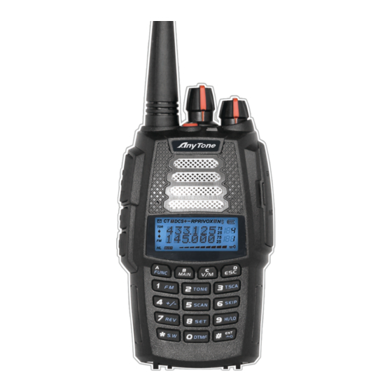
GETTING ACQUAINTED LCD Display On LCD display screen, you will see various icons which stand for the selected functions and sometimes you may forget the meaning of them. Here you will find the following table extremely useful. Frequency VOX Function Reverse Offset Frequency Scan Skip... - Page 22 GETTING ACQUAINTED DCIN...
- Page 23 GETTING ACQUAINTED Antenna Channel switch POWER/VOLUME switch Rotate it clockwise to turn on transceiver, rotate it anticlockwise until heard "click" to turn off the transceiver. When transceiver is power on, rotate it clockwise to increase volume, anticlockwise to reduce volume. Emergency Alarm Under standby state, press and hold Emergency alarm key for 3 seconds to start alarm function, power off transceiver to exit alarm.
-
Page 24: Basic Operations
BASIC OPERATIONS Turn the Radio On & OFF Under power-off state, please turn [POWER] / [VOLUME] clockwise to turn on the transceiver. Under power-on state, please turn [POWER] / [VOLUME] anticlockwise to turn off the transceiver. Adjusting Volume Under power-on state, turn [POWER] / [VOLUME] to adjust volume. Clockwise- up, anticlockwise -down. -
Page 25: Switch Between Main Band And Sub Band
BASIC OPERATIONS Switch between Main band and Sub band Under standby state, press key to switch channel between Main band and Sub band. Arrow directs the current operational channel. Switch between Channel mode and VFO mode Under standby state, press key to set main band as Channel mode or frequency mode(VFO). -
Page 26: Frequency Input By Keypad
BASIC OPERATIONS NOTE: Channel step:2.5K, 5K, 6.25K, 10K, 12.5K, 20K, 25K, 30K and 50KHz in total 9 for optional. FM radio step frequency is 50K. Frequency Input by Keypad Under frequency mode or FM radio frequency mode, you can directly enter frequency through keypad. 1. -
Page 27: Squelch Off Momentary / Squelch Off
BASIC OPERATIONS Squelch Off Momentary / Squelch Off Side key [PF2] can be setup for Squelch off Momentary or Squelch off function by programming software. 1.Squelch off: Press [PF2] key, squelch circuit is not mute, back-ground noise can be heard. Press [PF2] key again, squelch circuit is mute. -
Page 28: Emergency Alarm
BASIC OPERATIONS NOTE: When press and hold PTT key, transceiver is transmitting if the red LED light is on, release PTT key to receive calls. Emergency Alarm Under standby state, press and hold alarm key until LCD displays "ALARM", Emergency alarm function is started. -
Page 29: Side Key [Pf2] Function Instruction
BASIC OPERATIONS Side key [PF2] function instruction 1. Squelch off: Press [PF2] key, squelch circuit is not mute, back-ground noise can be heard. Press [PF2] key again, squelch circuit is mute. 2. Squelch off Momentary: Press and hold [PF2] key, squelch circuit is not mute, back-ground noise can be heard. -
Page 30: Delete Channel
BASIC OPERATIONS Delete channel 1. Under standby state, press key, the top left corner of LCD displays " " icon, press key to switch into channel mode, channel number flashes. 2. Rotate channel switch to select desired deleting channel number. 3. -
Page 31: Shortcut Operations
SHORTCUT OPERATIONS Add/Cancel Optional signal decode function Under standby state, press key, the top left corner of LCD displays " " icon, press key, LCD displays " " icon, it means current channel add DTMF signal decode function. Repeat above operation, LCD still displays " "... -
Page 32: Offset Frequency Direction Setup
SHORTCUT OPERATIONS Offset Frequency Direction Setup Under standby state, press key, the top left corner of LCD displays " " icon, press key to choose offset frequency direction. There are 3 options, Positive offset, Minus offset, shut off offset. 1. (+) Positive offset: Indicates TX frequency is higher than RX frequency. When enable reverse function, the RX frequency is higher than TX frequency. -
Page 33: Channel Scan Skip
SHORTCUT OPERATIONS 2. Channel Scan Under channel mode, this function is used for monitoring signal of each channel in this mode. Press numeric key or key to exit. NOTE: ▼ Frequency scan is of all bands scan, it scans upwards as your STEPPING setting. ▼... -
Page 34: Tx Power Selection
SHORTCUT OPERATIONS 1. When LCD displays "R" icon, it means current arrow directed channel open the frequency reverse function, the TX frequency and RX frequency is interchanged, if CTCSS/DCS signaling is set, it will also interchange. 2. When "R" icon disappears, it means reverse function is close. TX Power selection Under standby state, press key, the top left corner of LCD displays "... -
Page 35: Dtmf Code Transmit And Enquiry
SHORTCUT OPERATIONS DTMF code Transmit and Enquiry 1. Press key, the top left corner of LCD displays " " icon, then press key, LCD displays DTMF data and group number (total 16groups) of current group. 2. Rotate channel switch to choose desired group and DTMF data, press PTT key to transmit selected DTMF signaling. -
Page 36: Single-Band Switching
SHORTCUT OPERATIONS Single-band Switching To reduce the interference from the sub-channel when the main channel be used. You can use single-band switching function, turn off the sub-channel bands quickly. 1. In standby mode, press the button, the radio will display the PC channel, and turn off the processor channel. -
Page 37: Function Menu Setup
FUNCTION MENU SETUP Menu 1-14 of this transceiver are channel operations. Channel operations temporarily changed the functions of current channel. When power off or channel has been changed, the relevant setup will be erased. Only under VFO mode, the channel operations will be saved until next change. Menu 15-32 is background operation, it is valid for all channels, the relevant setup will be saved until next change. -
Page 38: Ctcss/Dcs Decode Setup
FUNCTION MENU SETUP CTCSS/DCS Decode Setup If this function is enabled, you can ignore (can not hear) other unrelated call at the same frequency. 1. Press key, the top left corner of LCD displays " " icon, then press key to enter into function menu. 2. -
Page 39: 5Tone Encode Group Selection
FUNCTION MENU SETUP 3. Press key to choose CTCSS,DCS or OFF, when DCS signaling is selected, press key to choose DCS positive or inverse code. 4. Rotate channel switch to choose desired CTCSS/DCSencode/decode. CTCSS: 62.5Hz~254.1Hz, 51groups in total, and 1 group user-defined code. DCS: 000N-777I, 232 groups in total. -
Page 40: Optional Signaling Setup
FUNCTION MENU SETUP Optional signaling setup DTMF and 5TONE functions are similar to CTCSS/DCS, it has special call functions, such as ANI, PTT ID, All call, Alarm, remotely kill, remotely stun and remotely waken, etc.. 1. Press key, the top left corner of LCD displays " "... -
Page 41: Frequency Step Size Setup
FUNCTION MENU SETUP SQ: When current channel receives matching RF signals, transceiver can hear the talking from the other party. CT/DCS:When current channel receives matching RF signals and matching CTCSS/ DCS signaling, transceiver can hear the talking from the other party. TONE: When current channel receives matching RF signals and matching optional signaling, transceiver can hear the talking from the other party. -
Page 42: Wide / Narrow Band Selection
FUNCTION MENU SETUP NOTE: This function item will hide automatically when main band and sub main band are under channel mode. Wide / Narrow Band Selection According to the national conditions of various countries, it can be set for communication by wide band or narrow band. -
Page 43: Talk Around On/Off
FUNCTION MENU SETUP 4. Press key or key to confirm and exit. Talk Around ON/OFF When this function is on, transceiver will cut communication with repeater. 1. Press key, the top left corner of LCD displays " " icon, then press key enter into function menu. -
Page 44: Editing Channel Name
FUNCTION MENU SETUP 3. Rotate channel switch to choose desired offset frequency. Frequency range is 00-70MHz. 4. Press key or key to confirm and exit. Editing Channel name 1. Press key, the top left corner of LCD displays " " icon, then press key enter into function menu. -
Page 45: Tx Off
FUNCTION MENU SETUP BUSY: Carrier wave lock, transmitting is prohibited when received matching carrier wave. REPEAT: Signaling lock, transmitting is prohibited when received matching carrier but with unmatching CTCSS/DCS. OFF: Close BCLO function. 4. Press key or key to confirm and exit. TX OFF When this function is on, [PTT] key is unavailable. -
Page 46: Sub Band Display Setup
FUNCTION MENU SETUP 1. Press key, the top left corner of LCD displays " " icon, then press key enter into function menu. 2. Press key to choose NO. 15 function item, it shows "BAND" on LCD. 3. Rotate channel switch to choose desired setup. ON: Band limit is enabled. -
Page 47: Keypad Voice Prompt Setup
FUNCTION MENU SETUP Keypad Voice Prompt Setup 1. Press key, the top left corner of LCD displays " " icon, then press key enter into function menu. 2. Press key to choose NO. 17 function item, it shows "BEEP" on LCD. 3. -
Page 48: Voice Operated Transmission (Vox) Setup
FUNCTION MENU SETUP Voice Operated Transmission (VOX) Setup When this function is on, the transmitting can be started by voice, no need to press [PTT] key. 1. Press key, the top left corner of LCD displays " " icon, then press key enter into function menu. -
Page 49: Automatic Power Off Time Setup
FUNCTION MENU SETUP Automatic Power Off Time setup When this function is on, transceiver will automatic power off when reach the preset time. 1. Press key, the top left corner of LCD displays " " icon, then press key enter into function menu. -
Page 50: Squelch Level Setup
FUNCTION MENU SETUP Squelch level setup This function is used for setup intensity of receiving signals, transceiver will hear calls when receiving signal intensity achieve preset data, otherwise, transceiver will keep mute. 1. Press key, the top left corner of LCD displays " "... -
Page 51: Function Icon Stay Time Setup
FUNCTION MENU SETUP Function Icon Stay Time Setup 1. Press key, the top left corner of LCD displays " " icon, then press key enter into function menu. 2. Press key to choose NO. 25 function item, it shows "FTIME" on LCD. 3. -
Page 52: Lcd Backlight Color Setup
FUNCTION MENU SETUP AUTO: Backlight will automatic closed after a period. OFF: Always off. ON: Always on. 4. Press key or key to confirm and exit. LCD Backlight Color Setup There are three kinds of backlight color for optional. 1. Press key, the top left corner of LCD displays "... -
Page 53: Tone Pulse Frequency Selection
FUNCTION MENU SETUP 4. Press key or key to confirm and exit. NOTE: When current channel add 5TONE to be optional signaling, LCD displays 5TONE self ID code, otherwise displays DTMF self ID code. Tone Pulse Frequency Selection This function is used for waking up sleeping repeater, it needs a certain intensity of Tone Pulse to wake up sleeping repeater. -
Page 54: Fm Radio
FUNCTION MENU SETUP 1:2 The standby time between normal working state and battery saving mode is 1:2 1:3 The standby time between normal working state and battery saving mode is 1:3 1:5 The standby time between normal working state and battery saving mode is 1:5 1:8 The standby time between normal working state and battery saving mode is 1:8 AUTO: Battery save ratio is adjusting automatically. -
Page 55: Pf1 Key Function Setup
FUNCTION MENU SETUP reception. Also when FM Radio is on, quick press of key will mute / un-mute FM Radio. 2. FM Radio activates in either VFO Mode and Channel Mode. In Channel Mode, LCD shows received frequency with saved channel number to right hand side. In VFO Mode, only received frequency will show. -
Page 56: Senior Function Operations
SENIOR FUNCTION OPERATIONS Display Mode Setup There are three kinds of display modes for optional. 1. Press [PF2] key to turn on radio, hold [PF2] key until transceiver emits beep. 2. Press key to choose No. 01 function item, it shows "DSP" on LCD. 3. -
Page 57: Cloning Cable
SENIOR FUNCTION OPERATIONS OFF: No operations. FACT: Resume all items to factory default, including channel and background settings. INIT: Resume background settings to factory default, channel operations are keeping. 4. Press key to exit current selection. 5. Press key to confirm current selection. Cloning Cable This feature will copy the programmed data and parameters from the master unit to slave units. - Page 58 SENIOR FUNCTION OPERATIONS [Settings: Master side] 1. Press the [PF1] side key to Power on, the display shows "CLONE", the master unit enters into copy mode. 2. Press [PF1] key, the display appears "CLONE XX" XX stands for the data amount being cloned.
-
Page 59: Additional Functions For Version C And D
ADDITIONAL FUNCTIONS FOR VERSION C AND D Cross-Band Repeater( Version C and D) Radio will function as cross band repeater when in this mode. 1. Set Main-Band and Sub-Band to desired UHF and VHF frequencies. 2. Power radio off. 3. Press and hold both [PF1] and while powering radio on. -
Page 60: Mute Setup (Version C And D)
ADDITIONAL FUNCTIONS FOR VERSION C AND D Mute Setup (Version C and D) In UV or VU mode, when one band is RX, the other band is TX, turn on this function will mute the speaker of RX band. 1. Press key, LCD shows "... -
Page 61: Msk Encode Group Selection(Version D)
ADDITIONAL FUNCTIONS FOR VERSION C AND D MSK encode group selection(Version D) 1. Press key, LCD shows " " icon, then press key to enter into function menu. 2. Press key to choose NO.06 function item, it shows "MSKENC" on LCD. 3. -
Page 62: Frequency Hopping (Version D)
ADDITIONAL FUNCTIONS FOR VERSION C AND D Frequency Hopping (Version D) When [PF1] key programmed as FHSS, press [PF1] key will turn on the frequency hopping function. When press [PTT] key, LCD shows "FHSS", radio will communicate in the preset frequency hopping range. Note: The receiver and transmitter must have same hopping frequency, and must setup the MSK decode. -
Page 63: Programming Software Starting (Takes Windows Xp System For Example)
Programming software starting (Takes Windows XP system for example) 1.Double Click "QPS398UV setup.exe", then go on installing as computer command. 2.Click "START" menu of computer, choose "USB To COM" in QPS398UV item and click it. Please install USB To Comport drive program as computer command. -
Page 64: Technical Specification
TECHNICAL SPECIFICATION General Receiving Part VHF: 144~146MHz (EX: 136~174MHz) Wide band Narrow band Frequency Range UHF: 350~390MHz (Type: B only) Sensitivity ≤0.25μV ≤0.35μV UHF: 430~440MHz (EX: 400~480MHz) (12dB SINAD) Channel Capacity 200 channels Adjacent Channel ≥65dB ≥60dB 25KHz (wide band) Selecitvity Channel Spacing 12.5KHz (narrow band) -
Page 65: Trouble Shooting Guide
TROUBLE SHOOTING GUIDE Problem Corrective Action A.The battery may be exhausting. Recharge or replace the battery. B.The battery may not be installed correctly. Remove the battery No power and install it again. C.The power switch is broken; send it to local dealers to repair. D.Battery touch is broken;... - Page 66 TROUBLE SHOOTING GUIDE Can not power on or frequent Check weather the battery touch is out of sharp or broken. power off The receiving sound gets low or Check weather the MIC is stoppage. Otherwise, please contact with intermittent local dealers to repair it. A.Out of communication range or obstruct by tall buildings or in big Receiving intermittent with in big noise.
-
Page 67: Attached Chart
ATTACHED CHART CTCSS Frequency Chart 62.5 94.8 136.5 177.3 218.1 67.0 97.4 141.3 179.9 225.7 69.3 100.0 146.2 183.5 229.1 71.9 103.5 151.4 186.2 233.6 74.4 107.2 156.7 189.9 241.8 77.0 110.9 159.8 192.8 250.3 79.7 114.8 162.2 196.6 254.1 82.5 118.8 165.5... -
Page 68: 1024 Groups Dcs Frequency Chart
ATTACHED CHART 1024 groups DCS frequency chart... - Page 69 ATTACHED CHART...
- Page 70 ATTACHED CHART NOTE: N stands for positive code. I stands for inverted code. 1024 groups of DCS in total.
Need help?
Do you have a question about the AT-398UV and is the answer not in the manual?
Questions and answers