Table of Contents
Advertisement
Quick Links
Advertisement
Table of Contents

Subscribe to Our Youtube Channel
Related Manuals for AnyTone AT-598


Summary of Contents for AnyTone AT-598
- Page 1 AT-598 Mobile Radiao FCC ID:T4KAT598V...
- Page 2 If an abnormal odor or smoke is detected coming from the transceiver, turn OFF the power immediately. Contact an Anytone service station or your dealer. Do not transmit with high output power for extended periods; the transceiver may overheat.
-
Page 3: Table Of Contents
CONTENTS ..........1 Transmitting Optional Signaling ............13 Channel Edit ..................13 Supplied Accessories/Optional Accessories.....2 Channel Delete ................13 Supplied Accessories............... 2 Shortcut Operations.............14 Optional Accessories ............... 2 Squelch Off/Squelch Off Momentary..........14 ..............3 Squelch Level Setup ................ 14 Mobile Installation ................3 DC Power Cable Connection ............ - Page 4 CONTENTS Squelch Level .................. 27 Band-width Selection ............... 20 Optional Signaling ................27 TX OFF Setup.................. 21 Scan Skip ..................28 Busy Channel Lockout ..............21 Frequency/Channel Scan ............... 28 Editing Channel Name ..............21 Busy Channel Lockout ..............28 Reverse TX/RX ................
- Page 5 New and Innovative Features 598 Mobile Radio has nice housing, stoutness & stability, advanced and reliable functions, perfect & valuable. This amateur mobile radio especially designs for drivers and it pursues company philosophy of innovation and practicality. More functions as follows: There are Amateur operation mode and Professional operation mode for option.
-
Page 6: Supplied Accessories/Optional Accessories
Supplied Accessories Supplied Accessories After carefully unpacking the transceiver, identify the items listed in the table below. We suggest you keep the box and packaging. Transceiver Microphone (QHM-03) DC Power Cable with User Manual (with DTMF keyboard) Fuse Holder(QPL-01) Car Antenna Car Antenna (QCA-01) (QCA-01) -
Page 7: Mobile Installation
Initial Installation Determine the appropriate angle of the transceiver, using the 3 screw Mobile installation hole positions on the side of the mounting bracket. To install the transceiver, select a safe, convenient location inside your vehicle that minimizes danger to your passengers and yourself while the vehicle is in motion. -
Page 8: Dc Power Cable Connection
Initial Installation DC Power Cable Connection Locate the power input connector as close to the transceiver as possible. Mobile Operation Black The vehicle battery must have a nominal rating of 12V. Never connect the transceiver to a 24V battery. Be sure to use a 12V Connect the DC power cable to the transceiver's power supply vehicle battery that has sufficient current capacity. - Page 9 Initial Installation Use the supplied DC power cable to connect the transceiver to a To turn on the unit, press the power switch manually while it is illuminated. (While ignition key is at ACC or ON position) regulated power supply. When the ignition key is turned to ACC or ON position with the Do not substitute a cable with smaller gauge wires.
-
Page 10: Power Supply Voltage Display
Initial Installation REPLACING FUSES If the fuse blows, determine the cause, then correct the problem. After the problem is resolved, replace the fuse. If newly installed fuses continue to blow, disconnect the power cable and contact your autho- rized mobile radio dealer or an authorized mobile radio servi-... -
Page 11: Accessories Connections
Initial Installation Accessories Connections Microphone For voice communications, connect a microphone equipped with an External Speaker 8-pin modular plug into the modular socket on the front of the main If you plan to use an external speaker, choose a speaker with an supplied microphone hanger in an appropriate location using the mono (2-conductor) plug. -
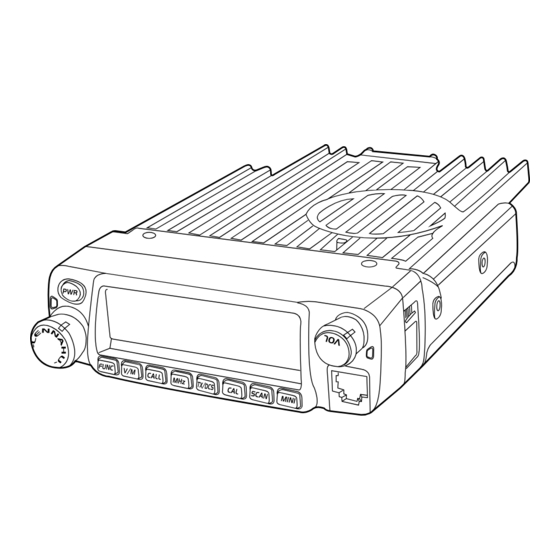
Page 12: Front Panel
Getting Acquainted Front panel Press key until key. NO. KEY FUN/SET V/M/MW Stores data into channels MHz/SHIFT Sets offset direction and offset frequency TS/DCS/LOCK Sets Keypad lock function power SQL/D Compander mode on/off Press NO. KEY NO. KEY Pow(Power) Power on/Off Pow(Power) Reset to factory default settings V/M/MW... -
Page 13: Rear Panel
Getting Acquainted Rear panel NO. KEY Squelch level. In channel mode. Indicates the channel number in channel mode. Channel skip. Decimal point Indicates the decimal point of frequency and the Decimal point scanning function. Indicates the frequency or memory name. Signal is being received or monitor. -
Page 14: Microphone
Getting Acquainted microphone MIC Connector Diagram(in the front view of connector) -
Page 15: Working Mode (Amateur Transceiver Or Professional Transceiver)
WORKING MODE (AMATEUR TRANSCEIVER OR PROFESSIONAL TRANSCEIVER) According to practical application, you can set the radio works as Amateur Transceiver mode or Professional Transceiver mode. There This mode shows only frequency on are also 2 levels operation menu to set functions as you need. It is easy the display. -
Page 16: Basic Operations
Basic Operations frequency in screen will be auto-hidden. In this status, turn selector Switching The Power On/Off PWR KEY knob or Microphone [ ] key will increase or decrease According to the option selected during installation frequency quickly by 1MHz step. Press the switch or turn the ignition key to Under channel mode, you can change the current channel to the... -
Page 17: Transmitting Tone-Pulse
Basic Operations Please hold the microphone approximately 2.5-5.0cm from your lips , Channel Delete and then speak into the microphone in your normal speaking voice to Under channel mode, turn selector knob to select channel which get best timbre. you want to delete. Press and hold [PTT] key, LED lights RED and power intensity showed in Press key and... -
Page 18: Shortcut Operations
Shortcut Operations squelch off/squelch off momeNTARY In VFO mode, press for 1s to enter into frequency scan. key programmed as Squelch Off or Squelch Off Momentary to monitor the weak signal. Turn selector knob or press Microphone ] key to change scan direction. Squelch Off: Press key to disable squelch, press key again... -
Page 19: Ctcss Scan
Shortcut Operations When LCD appears icon, it means Compander (Decrease the background noise and ENHANCE current channe can be set with DCS AUDIO CLARITY) encode and decode together, turn selector knob or press Microphone's [ ] to select Compander function will decrease the background noise and enhance desired DCS encode and decode. -
Page 20: Offset Direction And Offset Frequency Setup
Shortcut Operations KEYPAD LOCKOUT Offset Direction and offset frequency setup Avoiding unintentional operation, this function will lock main keys, all Repeater receives a signal(UP-LINK) on one frequency and re-transmits keys except key are invalid. on another frequency(DOWN-LINK). The difference between these two Press key until LCD displays icon,... -
Page 21: Transmitting Edited Dtmf Tones In The Auto-Dialer Memory
Shortcut Operations 01-16. Press key to enter into editing of current group, press MIC's numeric keys to set your desired data. The display scrolls when the 7th digit is entered. The numbers 0-9, --, A-D, * and # can be stored up to a total of 23 digits. -
Page 22: General Setting
General Setting Press and hold key for over 2s to enter general setting menu. features such as ANI, PTT ID, group call, remotely stun, remotely kill, waken,...etc.. The signalling edition must be done through programming Press to select the desired function option. software. -
Page 23: Sending 2-Tone Call
General Setting Press directly to transmit the pre-stored 5-Tone signaling. Press key to choose No.04 menu, LCD displays "5TON XX", "XX" In 5Tone signaling mode, press for 2s until LCD displays indicates the group in the list. "AN---", turn selector knob to select desired digit(caller ID). In Turn selector knob to select the desired sending 5TONE group, this mode, press to confirm exist digit and move cursor to... -
Page 24: Band-Width Selection
General Setting Press key to choose No.06 menu, LCD displays "SPK--SQ". Turn selector knob to select the desired combination. If select "SQ", it indicates you can hear the calling from caller when receive a matching carrier. If LCD displays " CTC", it indicates you can hear the calling from caller when receive a matching carrier and CTCSS/DCS signaling. -
Page 25: Tx Off Setup
General Setting RL: Enable BTLO, transmitting is inhibited when current channel TX OFF SETUP receives a matching carrier but dis- Disable this function, it is invalid to press PTT, current channel only matching CTCSS/DCS. Press [PTT] works in RX mode. to emit error voice prompt and back to receiving status. -
Page 26: Talk Around
General Setting Press key to choose No.14 menu, LCD displays "COMP- Press key to choose No.12 ". menu, LCD displays " ". Turn selector knob to select the desired Turn selector knob to select the desired setting. setting. Enable compander Enable Frequency Reverse Disable Frequency Reverse. -
Page 27: Radio's 5Tone Self Id Enquiry
General Setting menu, LCD displays "D--XXX", "XXX" is radio's DTMF SELF ID. TOT (Time-out timer) Press The time-out timer limits the amount of transmitting time. When you reach the time limit which has been programmed by your dealer, your transmission will be cut off. In order to transmit again, you must release Radio's 5TONE SELF ID ENQUIRY PTT button to reset the timer. -
Page 28: Dtmf Transmitting Time
General Setting Auto power off after 2h Disable Auto power off Press , then turn selector knob also can select the desired squelch level. Press If the transceiver has set at higher squelch level, it may fail to hear DTMF Transmitting Time the calling. -
Page 29: Pilot Frequency
General Setting Turn selector knob to select the desired LCD backlight brightness Press key to choose No.26 menu, LCD displays 1-32 total 32 level backlight brightness. " ". Press Turn selector knob to select the desired mode. Frequency+Channel mode(Amateur transceiver mode). Pilot Frequency C h a n n e l m o d e ( P r o f e s s i o n a l This function uses to start repeater. -
Page 30: Address List
General Setting Press and hold key for over 2s to enter general setting menu. Address list You store desired ID and corresponding ID name in address list. The Press key to choose No.29 LCD displays ID corresponding name if radio received ANI calling and menu, LCD displays "RESTORE". -
Page 31: Microphone Operation
Microphone Operation Switches between VFO and channel mode In standby, press key to switch between channel mode and Frequency mode (VFO). Short Calling In standby, press to transmit the selected DTMF/2TONE/5TONE in current channel. :In standby, press , LCD displays DTMF data and group. -
Page 32: Scan Skip
Microphone Operation Press [ ] to select the desired value. displays " ", it indicates 5Tone function Enable BCLO, Carrier lockout, transmitting is inhibited when enable. current channel receives a matching carrier; press [PTT] to emit error voice prompt. This function can be temporarily used in channel mode. Once the Enable BTLO, transmitting is inhibited when current channel radio is turned off or switched to another channel, the temporary receives a matching carrier but dis-matching CTCSS/DCS. -
Page 33: Tot (Time-Out Timer)
Microphone Operation TOT (Time-out timer) Talk Around By Talk Around function, you can directly communicate with other radios The time-out timer limits the amount of transmitting time. When you reach the time limit which has been programmed by your dealer, your in your group in case the repeater is not activated or when you are out of transmission will be cut off. -
Page 34: Lcd Backlight
Microphone Operation LCD Backlight In standby status, press , then press LCD displays "LAMP-XX". Press [ ] to select desired backlight brightness(1-32 levels). -
Page 35: Long-Distance Anti-Theft Alarm
Long-distance Anti-theft Alarm This function is mainly use for simple anti-theft alarm device in vehicles. When the alarm cable QL-01(A) or QL-01(B) is removed from the When the transceiver be removed in an improper manner, the transceiver will emit and transmit alarming and background voice to system and and will alarm as programmed. -
Page 36: Cable Clone
Cable Clone This feature will copy the programmed data and parameters in the master unit to slave units. It copies the parameters and memory program settings. Press and hold key, then press key to enter into cloning mode, LCD displays "CLONE". Master/Slave stereo plug,3.5mm plug DATA TX/RX Press master unit's [PTT] key, LCD displays "... -
Page 37: Xp System)
Programming Software Installing and Starting (in windows XP system) Double click "QPS598 setup.exe", then follow the installing instruction. Install USB Cable Driver Programme (As pic 1) Click start menu in computer, under "ALL PROGRAMS" menu, choose and click "USB To Com port" in QPS598 program, install "USB To Com port"... -
Page 38: Maintenance
Maintenance Default Setting after Resetting(VHF) Trouble Shooting Problem Possible Causes and Potential Solutions DCS encode AT598 and decode + and - polarities of power connection Power is on, nothing are reversed. Connect red lead to plus VFO frequency 145.00MHz DCS code 023N appears on Display. - Page 39 Specifications General band VHF: 136-174MHz Frequency Range Sensitivity (12dB Sinad) Number of Channels 200 channels Selectivity Intermodulation Channel Spacing 12.5K Audio Response +1~-3dB(0.3~2.55KHz) 5KHz 6.25KHz, 8.33KHz, 10KHz, 12.5KHz, Phase-locked Step Hum & Noise Operating Voltage 13.8V DC ±15% Audio distortion Squelch Carrier/CTCSS/DCS/5Tone/2Tone/DTMF Audio power output...
-
Page 40: Attached Chart
Attached Chart 50 groups CTCSS Tone Frequency(Hz) 1024 groups DCS Code. 67.0 79.7 94.8 110.9 131.8 156.7 171.3 186.2 203.5 229.1 69.3 82.5 97.4 114.8 136.5 159.8 173.8 189.9 206.5 233.6 71.9 85.4 100.0 118.8 141.3 162.2 177.3 192.8 210.7 241.8 74.4 88.5 103.5 123.0 146.2 165.5 179.9 196.6 218.1 250.3 77.0 91.5 107.2 127.3 151.4 167.9 183.5 199.5 225.7 254.1... - Page 41 Attached Chart N is positive code, is negative code, total: 232groups.
- Page 42 SAFETYTRAININGINFORMATION Your radio generators RF electromagnetic energy during Qixiang Electron Science & Technology Co.,Ltd. transmit mode.This radio is designed for and classified as“Occupational Use Only”,meaning it must be used only during the course of employment by individuals aware of the hazards,and the ways To Minimize Such hazards. This radio is NOT intended for use by the“General Population”...
- Page 43 INFORMATION RF exposure limits. A proper antenna is the antenna supplied with this manufacturer for use with this radio. This radio generates RF electromagnetic energy during transmission. DO NOT transmit for more than 50% during the time of employment This radio is designed for and classified as “Occupational Use Only”, meaning it must be used only during the course of employment by (50% duty cycle or less).
Need help?
Do you have a question about the AT-598 and is the answer not in the manual?
Questions and answers