Table of Contents
Advertisement
Quick Links
CONTENTS
Introduction .............................................. 1
Mount Controller ........................................ 1
Connect Sensors and Equipment .................. 2
Install (Optional) Override Boards ................. 3
Connect (Opt.) Expansion Modules ............... 4
Connect (Opt.) Ethernet Network .................. 4
Connect (Optional) MS/TP Network............... 4
Select End Of Lines (EOL) ............................ 5
Connect Power .......................................... 5
Power and Communication Status ................. 5
MS/TP Network Isolation Bulbs .................... 7
Configure/Program the Controller ................. 7
Sample (BAC-5901) Wiring .......................... 8
Replacement Parts ..................................... 9
Important Notices ...................................... 9
INTRODUCTION
Complete the following steps to install a KMC Conquest
BAC-5900 Series BACnet General Purpose Controller.
For controller specifications, see the
kmccontrols.com. For additional information, see the
KMC Conquest Controller Application
MOUNT CONTROLLER
NOTE: Mount the controller inside a metal
enclosure for RF shielding and physical
protection.
NOTE: To mount the controller with screws on a
flat surface, complete the steps in
Flat Surface on page
controller on a 35 mm DIN rail (such as
integrated in an
complete the steps in
page
1.
On a Flat Surface
1. Position the controller on a flat surface so that the
color-coded terminal blocks
for wiring after the controller is mounted.
KMC Controls, 19476 Industrial Drive, New Paris, IN 46553
data sheet
at
Guide.
On a
1. Or to mount the
HCO-1103
enclosure),
On a DIN Rail on
are easy to access
1
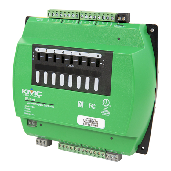
BAC-5900 Series Controller
NOTE: The black terminals are for power. The
green terminals are for inputs and outputs.
The gray terminals are for communication.
2. Screw a #6 sheet metal screw through each corner
of the controller.
2
1
On a DIN Rail
1. Position the DIN rail
terminal blocks are easy to access for wiring after
the controller is mounted.
2. Pull out the DIN latch
3. Position the controller so that the top four tabs
of the back channel rest on the DIN rail.
3
4. Lower the controller against the DIN rail.
/
877.444.5622
/
Fax: 574.831.5252
Installation Guide
so that the color-coded
3
until it clicks once.
4
/
www.kmccontrols.com
2
5
5
4
Advertisement
Table of Contents

Subscribe to Our Youtube Channel
Related Manuals for KMC Controls BAC-5900 Series


Summary of Contents for KMC Controls BAC-5900 Series
-
Page 1: Table Of Contents
4. Lower the controller against the DIN rail. 1. Position the controller on a flat surface so that the color-coded terminal blocks are easy to access for wiring after the controller is mounted. KMC Controls, 19476 Industrial Drive, New Paris, IN 46553 877.444.5622 Fax: 574.831.5252 www.kmccontrols.com... -
Page 2: Connect Sensors And Equipment
(yellow) ROOM SENSOR port of the controller. 4. Connect equipment to the green (output) terminals . See Sample (BAC-5901) Wiring on page 8 and BAC-5900 series videos on the KMC Conquest Controller Wiring playlist. BAC-5900 Series Controller Installation Guide 925-019-01J... -
Page 3: Install (Optional) Override Boards
6700 series videos in the KMC Conquest with a jumper installed on the two pins closest Controller Wiring playlist. to the output terminal blocks. Only remove a jumper if an override board will be installed. BAC-5900 Series Controller Installation Guide 925-019-01J... -
Page 4: Connect (Opt.) Expansion Modules
CONNECT (OPT.) EXPANSION MODULES NOTE: Up to four CAN-5901 I/O expansion modules can be connected in series (daisy-chained) to a BAC-5900 series controller to add additional inputs and outputs. 1. Wire the gray EIO (Expansion Input Output) terminal block of the BAC-5900 series controller to the gray EIO terminal block of the CAN-5901. -
Page 5: Select End Of Lines (Eol)
Power (Controller) Connections section of the KMC Conquest Controller Application Guide. NOTE: For more information, see Sample (BAC- 5901) Wiring on page 8 and the BAC- 5900 series videos in the KMC Conquest Controller Wiring playlist. BAC-5900 Series Controller Installation Guide 925-019-01J... -
Page 6: Power And Communication Status
• The EIO LED flashes when the controller is communicating with the EIO network • The EIO LED remains OFF when the (powered) controller is not communicating with the EIO network. Check the power and EIO network connections. BAC-5900 Series Controller Installation Guide 925-019-01J... -
Page 7: Ms/Tp Network Isolation Bulbs
CONFIGURE/PROGRAM THE CONTROLLER hosted on a remote web server, but not in the controller. See the table for the most relevant KMC Controls tool for **Conquest Ethernet-enabled “E” models with the configuring, programming, and/or creating graphics for latest firmware can be configured with an HTML5 the controller. -
Page 8: Sample (Bac-5901) Wiring
Ethernet patch cord. sensors, 0–12 VDC, or 4–20 mA. NOTE: For more information about connections to expansion modules, see the installation guide for the From CAN-5901. Ethernet Previous Next CAN-5901 I/O Expansion Module(s) Controller Controller BAC-5900 Series Controller Installation Guide 925-019-01J... -
Page 9: Replacement Parts
Terminal Blocks DIN Clips this document. (1) Black 2 Position (2) Small The KMC logo is a registered trademark of KMC Controls, (2) Grey 3 Position (1) Large Inc. All rights reserved. (2) Green 3 Position The KMC Connect Lite™ app for NFC configuration...
Need help?
Do you have a question about the BAC-5900 Series and is the answer not in the manual?
Questions and answers