Table of Contents
Advertisement
Quick Links
Installation Guide (6/3 Outputs)
Quick Start
CAUTION
This document is for 6-relay, 3-analog-output,
6-external-input BAC-12xx63/13xx63/14xx63 series
THESE MODELS ARE NOT COMPATIBLE
ONLY.
WITH THE BACKPLATES OF OLDER BAC-10000
SERIES FLEXSTATS (WITH ONLY 3 EXTERNAL
INPUTS)!
If replacing an older 3-input FlexStat,
replace the backplate as well. See other installation
guides for other models.
To select and use a FlexStat in an application:
1. Select the appropriate model for the in-
tended application and options (see the
12xxxx/13xxxx/14xxxx Series FlexStat Data
Sheet).
2. Mount and wire the unit (see this Installation
Guide).
3. Configure/program the unit (see the
Operation
and the
4. If necessary, troubleshoot any issues (see the
FlexStat Operation
5. Operate the unit (see the
Guide).
NOTE: This document gives basic mounting,
wiring, and setup information only. For
configuration, programming, operation,
and other information, see the KMC
Controls web site for the latest documents.
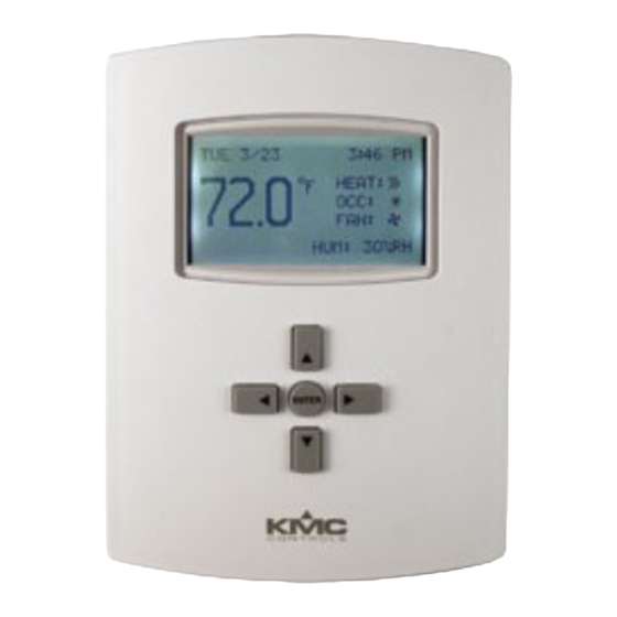
Models
BAC-12xxxx (shown)
BAC-13xxxx/14xxxx
A
EIA-485 data
B
port (for quick
network access)
Terminal blocks on
backplate (rotated on
BAC-13xxxx/14xxxx)
Illustration 1—Dimensions and Installation
BAC-12xx63/13xx63/14xx63 Series FlexStat
BAC-
FlexStat
Application
Guide).
Guide).
FlexStat Operation
Dimensions in Inches (mm)
A
B
C
1.125 (29)
4.192 (106)
5.551
(141)
1.437 (36.5)
5.192 (132)
Embossed "UP" indicator
Cover locking hex screws
BAC-12xx63/13xx63/14xx63 Series FlexStat
6 Relays, 3 Analog Outputs, 6 External Inputs
Mounting
For optimum temperature sensor performance,
the FlexStat must be mounted on an interior wall
and away from heat sources, sunlight, windows,
air vents, and air circulation obstructions (e.g.,
curtains, furniture). Additionally, for a model with
an occupancy sensor option, install it where it will
have unobstructed view of the most typical traffic
area. (See the
FlexStat Application Guide
information.)
If replacing an existing thermostat, label wires as
needed for reference when removing the existing
thermostat.
1. Complete rough-in wiring at each location prior
to thermostat installation. Cable insulation must
meet local building codes.
CAUTION
To prevent mounting screw heads from touching the
circuit board in the thermostat, use only the mounting
screws supplied by KMC Controls. Using other screws
may damage the FlexStat. Do not turn screws in
farther than necessary to remove the cover.
2. If the cover is locked on the backplate, turn the
hex screws in the bottom and top of the FlexStat
CLOCKWISE until they (just) clear the cover.
(See Illustration 1.) Pull the cover away from the
backplate (mounting base).
3. Route the wiring through the backplate.
4. With the embossed "UP" and arrows toward the
ceiling, fasten the backplate to a wall handy-box.
BAC-12xxxx models mount directly on vertical 2
x 4 inch boxes, but they require an HMO-10000/
HMO-10000W wall mounting plate for horizontal
or 4 x 4 boxes. BAC-13xxxx/14xxxx models mount
directly on any of those types of boxes.
5. Make the appropriate connections to the terminal
blocks. (See
6. Place the FlexStat cover over the backplate while
being careful not to pinch or dislodge any
wiring. Back the hex screws (counterclockwise)
out of the brackets until they engage the FlexStat
cover and hold it in place.
1
Connections and Wiring on page
™
for more
2.)
Installation Guide, Rev. F
Advertisement
Table of Contents

Related Manuals for KMC Controls FlexStat BAC-12 63 Series


Summary of Contents for KMC Controls FlexStat BAC-12 63 Series
- Page 1 Application Guide). circuit board in the thermostat, use only the mounting screws supplied by KMC Controls. Using other screws 4. If necessary, troubleshoot any issues (see the may damage the FlexStat. Do not turn screws in FlexStat Operation Guide).
-
Page 2: Connections And Wiring
Connections and Wiring Wiring Considerations MS/TP EOL (End-Of-Line) Termination • Because of the many connections (power, The controllers/thermostats on the physical ends of network, inputs, outputs, and their respective an EIA-485 wiring segment must have end-of-line grounds or switched commons), be sure wiring termination installed for proper network operation. -
Page 3: Input Connections
NOTE: To use a 4–20 current loop input or map NOTE: SC = Switched IP/Ethernet analog inputs as binary values, see the (relay) Common Network (Optional) FlexStat Application Guide. NOTE: IN1 and IN5–6 are reserved for internal sensors NOTE: To use a remote SAE-10xx CO sensor, see Outputs FlexStat Operation... -
Page 4: Maintenance
The FlexStat requires an external, 24 volt, AC power Application Guide. source. Use a KMC Controls Class-2 transformer to supply power. Connect the transformer’s neutral lead to the 24 VAC Common/–/C terminal and the AC phase lead to the 24 VAC Phase/ /R terminal. - Page 5 Applications Air Handler Unit (AHU)— Modulating Heat and Modulating Cool AHU LAYOUT NOTE: See also the RTU section for 2-stage options. REE-3211 or CVR11C-0/LD96200 Multi-Voltage Relay XEE-6311-075/6311-100 Transformer APPLICATION DEGREES SCALE: °F APP: AIR HANDLER NOTE: For MAT sensor use ADDITIONAL SETUP SET SWITCHES FOR...
-
Page 6: Heat Pump Unit (Hpu)
Heat Pump Unit (HPU)— HPU LAYOUT 1 or 2 Compressors with Auxiliary and Emergency Heat NOTE: For MAT sensor use with firmware earlier than R2.1.0.18, see the FlexStat Economizer Change of MAT to DAT Service Bulletin available on the KMC Partners web site. - Page 7 Roof Top Unit (RTU)— RTU 2H/2C LAYOUT 1 or 2 Heat and 1 or 2 Cool NOTE: For MAT sensor use with firmware earlier than R2.1.0.18, see the FlexStat Economizer Change of MAT to DAT Service Bulletin available on the KMC Partners web site.
- Page 8 Fan Coil Unit (FCU)— FCU 4-PIPE MODULATING LAYOUT 2 or 4 Pipe, Modulating or 2 Position NOTE: In firmware earlier than R2.1.0.18, 4-PIPE MODULATING OPTION an option for a (See the FCU—Other Options section on the next page for more options) DAT on IN2 was available for a XEE-6311-050 Transformer...
-
Page 9: Additional Resources
KMC Controls, Inc. makes no representations or warranties with respect to this document. In no event shall KMC Controls, Inc. be liable for any damages, direct or incidental, arising out of or related to the use of this document.
Need help?
Do you have a question about the FlexStat BAC-12 63 Series and is the answer not in the manual?
Questions and answers