Table of Contents
Advertisement
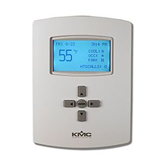
Installation and Configuration Guide
Contents
Contents .................................................................. 1
Mounting ................................................................ 1
Application Overview ............................................. 2
Roof Top Unit (RTU) ................................................ 3
Heat Pump Unit (HPU) ........................................... 4
Connections and Wiring .......................................... 5
Wiring Considerations ......................................... 5
Output Connections ............................................ 5
Input Connections ............................................... 6
Power Connection ............................................... 6
Network Wiring .................................................. 6
Network EOL (End-Of-Line) Termination ............ 7
Configuration and Operation .................................. 7
Configure the Application and Address ............... 7
Setpoints ............................................................. 8
Heat/Cool, Fan, Occupancy, and Override ......... 9
Schedules ............................................................ 9
Trends ................................................................. 9
Sequence of Operation ......................................... 10
Zone Hysteresis (Changeover) ........................... 10
Zone Status ....................................................... 10
Troubleshooting .................................................... 11
Maintenance ......................................................... 11
Customization ....................................................... 11
Remote (BAC-5051E) Interface ............................. 11
IoT (KMC Commander) Interface .......................... 12
Additional Resources ............................................ 12
Important Notices ................................................. 12
BAC-120063CW-ZEC FlexStat
NOTICE
OBSERVE PRECAUTIONS
FOR HANDLING
ELECTROSTATIC
SENSITIVE DEVICES
BAC-120063CW-ZEC FlexStat
Mounting
1. Complete rough-in wiring at each location prior
to the FlexStat's installation. Cable insulation
must meet local building codes.
CAUTION
To prevent mounting screw heads from touching
the circuit board in the thermostat, use only the
mounting screws supplied by KMC Controls.
Using other screws may damage the FlexStat.
Do not turn screws in farther than necessary to
remove the cover.
2. If the cover is locked on the backplate, turn the
hex screws in the bottom and top of the FlexStat
CLOCKWISE until they (just) clear the cover.
(See Illustration 1.) Pull the cover away from the
backplate (mounting base).
3. Route the wiring through the backplate.
4. With the embossed "UP" and arrows toward the
ceiling, fasten the backplate to a wall electrical
box. This FlexStat mounts directly on vertical 2 x
4 inch boxes but requires an HMO-10000W wall
mounting plate for horizontal or 4 x 4 boxes.
5. Make connections to the terminal blocks. (See
Connections and Wiring on page
6. Push the FlexStat cover over the backplate while
being careful not to pinch or dislodge any
wiring. Back the hex screws (counterclockwise)
out of the brackets until they engage the FlexStat
cover and hold it in place.
A
B
network access)
Terminal blocks
Cover locking hex screws
Dimensions in Inches (mm)
A
1.125 (29)
Illustration 1-Dimensions and Installation
1
Zoning Equipment Controller
5.)
Embossed "UP" indicator
EIA-485 data
port (for quick
on backplate
B
C
5.551 (141)
4.192 (106)
Installation and Configuration Guide, Rev. G
™
Advertisement
Table of Contents

Related Manuals for KMC Controls FlexStat BAC-120063CW-ZEC


Summary of Contents for KMC Controls FlexStat BAC-120063CW-ZEC
-
Page 1: Table Of Contents
Heat Pump Unit (HPU) ........... 4 the circuit board in the thermostat, use only the Connections and Wiring .......... 5 mounting screws supplied by KMC Controls. Wiring Considerations ......... 5 Using other screws may damage the FlexStat. Do not turn screws in farther than necessary to Output Connections .......... -
Page 2: Application Overview
Application Overview STE-140x SSS-101x Flow Sensor Temp Sensor Roof Top Unit Return Air Supply Air (RTU) To Low Pressure Port on Pitot Tube to H or L Port on SSS-100x Sensor CSP-4702 (Mounted Perpendicular to Air Flow) 1/4" Tubing To HI Optional Bypass Damper Port MS/TP Network... -
Page 3: Roof Top Unit (Rtu)
Roof Top Unit (RTU) (1 or 2 Heat and 1 or 2 Cool) CAUTION XEE-6111-050 or XEE-6112-50 Transformer Relays are for Class-2 voltages (24 VAC) only. Do not connect line voltage to the relays! Do not mistakenly connect 24 VAC to an analog output ground. -
Page 4: Heat Pump Unit (Hpu)
Heat Pump Unit (HPU) 1 or 2 Compressors with Auxiliary and Emergency Heat CAUTION XEE-6111-050 or XEE-6112-50 Transformer Relays are for Class-2 voltages (24 VAC) only. Do not connect line voltage to the relays! Do not mistakenly connect 24 VAC to an analog output ground. -
Page 5: Connections And Wiring
Connections and Wiring Wiring Considerations NOTE: IN1 and IN5–6 are NOTE: SC = Switched • Because of the many connections (power, reserved for internal sensors (relay) Common network, inputs, outputs, and their respective Outputs grounds or switched commons), be sure wiring Analog 9 Inputs is well planned before installation of conduit! -
Page 6: Input Connections
Open Relays Power Connection Illustration 6—Switched (Relay) Common and Relays Connect a KMC Controls 24 volt, Class-2 transformer to the power terminals on the FlexStat’s backplate: For the bank of three relays, there is one Switched (relay) Common connection (in place of the GND ter- 1. -
Page 7: Network Eol (End-Of-Line) Termination
Configuration and Operation Network EOL (End-Of-Line) Termination The controllers/thermostats on the physical ends of an EIA-485 wiring segment must have end-of-line WED 7/30 5:33 PM termination installed for proper network operation. COOL: (See Illustrations 7 and 8.) If a FlexStat is at the physi- OCC: Zone Information (# of cal end of the MS/TP network line, set both the EOL... -
Page 8: Setpoints
INSTANCE: 1000000 RTU or HPU. NAME: ZEC_FlexStat_1 3. Under ADDITIONAL SETUP > SENSORS, LOCATION: KMC Controls change IN2 from NONE to DAT. To configure the MAC address, from the Main Menu, select ADVANCED (enter password if needed) and SENSORS then COMMUNICATIONS. -
Page 9: Heat/Cool, Fan, Occupancy, And Override
that one day in the Individual Days menu SETPOINTS may be easier (two entries) than entering COOL DAT SETPOINT: 55° F schedules for each day separately in the HEAT DAT SETPOINT: 130° F DUCT ST STPT: 0.5 in H2O Individual Days menu (five entries). NOTE: The last overlapping entry overrides The optional duct static pressure setpoint is also in any other. -
Page 10: Sequence Of Operation
intervals) to an optional CSP-4702. • No Communication with a Zone (either there is a communication problem with a zone or no zone The Trend Viewer is available in the Main Menu to is connected) view the (last 256 samples of) data in tabular format. Software, such as KMC Connect or TotalControl, can The Zone Status screen also shows the Duct Status view the trend objects as graphs as well as change... -
Page 11: Troubleshooting
Customization Troubleshooting Additional customization can be done using KMC • For optimal temperature control, all spaces within a particular zone should be exposed to Connect, KMC Converge, or TotalControl. For ex- ample, a fan status switch (such as a KMC CSE-110x similar environmental factors (e.g., all border a or a CSE-120x) could be connected to IN3 (with the... -
Page 12: Iot (Kmc Commander) Interface
KMC Controls, Inc. makes no representations or warranties with respect to this document. In no event shall KMC Controls, Inc. be liable for any damages, direct or incidental, arising out of or related to the use of this document.
Need help?
Do you have a question about the FlexStat BAC-120063CW-ZEC and is the answer not in the manual?
Questions and answers